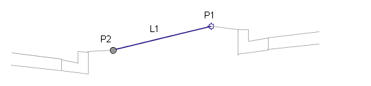
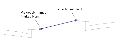
This subassembly is a general purpose utility that is similar to the LinkToMarkedPoint subassembly, and connects a link from the attachment point to a previously named marked point.
It can be used in a variety of situations, including connecting between adjacent roadways, where the relative offsets and elevations vary, or across a gore area between converging roadways. Use the MarkPoint subassembly if the connecting point has not already been named.
The primary difference between the LinkToMarkedPoint2 subassembly and the LinkToMarked point subassembly is in its application, when the marked point is on a different assembly baseline comparing to the link. Particularly if the two baselines in are not parallel, then the subassembly’s application will not be in the same plane, making the length of the link to marked point longer than it should be.
Attachment
The attachment point is at the beginning of the link. The link may go in any direction. The direction is determined by the location of the marked point relative to the attachment point.
Input Parameters
Note: All dimensions are in meters or feet unless otherwise noted. All slopes are in run-over-rise form (for example, 4 : 1) unless indicated as a percent slope with a “%” sign.
|
Parameter |
Description |
Type |
Default |
|---|---|---|---|
|
Marked Point Name |
Name of the marked point to connect to |
String |
None |
|
Link Codes |
A list of codes to be assigned to the link |
Comma-separated string |
Top, Datum |
|
Omit Link |
This parameter adds or removes the surface link. False to add the link, the start point, and the end point. True to add the end point only. |
True\False |
No |
Target Parameters
This section lists the parameters in this subassembly that can be mapped to one or more target objects, such as a surface, alignment, or profile object in a drawing. For more information, see in the AutoCAD Civil 3D User’s Guide Help.
Target Parameters: None.
Output Parameters
|
Parameter |
Description |
Type |
|---|---|---|
|
Begin Offset |
+/- offset of the beginning of the link |
Numeric |
|
Begin Elevation |
Elevation of the beginning of the link |
Numeric |
|
End Offset |
+/- offset of the end of the link |
Numeric |
|
End Elevation |
Elevation of the end of the link |
Numeric |
Behavior
The following diagram illustrates how the LinkToMarkedPoint2 subassembly functions, as well as how it displays in a cross-section for the offset baseline portion of the corridor.
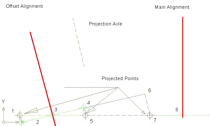
The LinkToMarkedPoint2 subassembly does either of the following, both of which have the same result:
- This subassembly projects point #7 onto line beta, resulting in point #6. Itthen computes the distance from #4 to #6. This is the marked point distance.
- This subassembly projects point #4 orthogonally from line beta onto line alpha, resulting in point #5. It then computes the distance from #5 to #7, and multiplies this by cosine (angle gamma). This is also the link-to-marked-point distance.
Note that the new LinkToMarkedPoint2 subassembly should not rely on the fact that point #7 will be at a constant offset at all stations along the main alignment.
Offset Baseline Corridor Cross-Section
Note the following:
- The cross-section sample line is orthogonal to the main baseline at point #8 (line alpha).
- The cross-section sample line is composed of one or more segments, with all segments collinear.
- The corridor point data for the offset portion of the corridor has offset values stored relative to the offset baseline.
- To project this corridor point data in the cross-section from line beta to line alpha for display in the cross-section view, the offset will need to be divided by cosine (angle gamma).
Note that using this approach, a lane subassembly on the offset portion of the corridor that is defined to be 3.5 meters in width, will be slightly wider than 3.5 meters in width when shown in the corridor cross-section.
Layout Mode Operation
In layout mode, this subassembly displays the link between the attachment point and the marked point.
Point, Link, and Shape Codes
None.
Coding Diagram