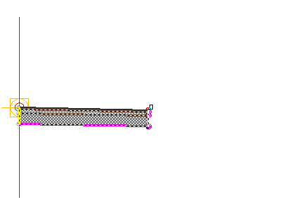
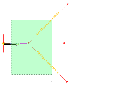
In this exercise, you will use some of the subassemblies that are shipped with AutoCAD Civil 3D to create an assembly for a basic crowned roadway with travel lanes, curbs, gutters, sidewalks, and slopes to an existing surface.
The corridor assembly you build will be used to create a corridor model in the Creating a Basic Corridor tutorial.
Create an assembly baseline
- Open Assembly-1a.dwg, which is located in the tutorials drawings folder.
- Click tab
 panel
panel  drop-down
 .
. - In the Create Assembly dialog box, for name, enter Primary Road Full Section. Click OK.
- When the ‘Specify assembly baseline location’ prompt is displayed on the command line, click in the rectangle under the profile views.
The viewport zooms to the assembly baseline, which looks like this:

Add a lane subassembly
- If the Tool Palette containing the subassemblies is not visible, click Home tab
 Palettes panel
  Tool Palettes
 .
. - In the tool palette, right-click the Tool Palettes control bar. Click Civil Metric Subassemblies.
- Click the Lanes tab.
- Click
 LaneSuperelevationAOR.
 - In the Properties palette, under ADVANCED, specify the following parameters:
- Side: Right
- Width: 3.5
- Potential Pivot: No
- In the drawing, click the marker point on the assembly baseline.
The right lane subassembly is now attached to the assembly baseline.
Add a curb subassembly
- In the Tool Palettes window, on the Curbs tab, click
 UrbanCurbGutterGeneral.
 - In the drawing, click the marker point at the top-right edge of the travel lane.
 Note:
Note:If you attach the subassembly to the wrong marker, you can move it to the correct location. Press Esc to exit subassembly placement mode. Select the subassembly you wish to move. A blue grip is displayed when the subassembly is selected. Select the grip, and then click the correct marker point.
Add a sidewalk subassembly
- In the Tool Palettes window, on the Basic tab, click
 Basic Sidewalk.
 - In the Properties palette, under ADVANCED, specify the following parameters:
- Side: Right
- Width: 1.5
- Buffer Width 1: 0.5
- Buffer Width 2: 0.5
- In the drawing, click the marker point at the top, back of the curb.

Add a daylight subassembly
- In the Tool Palettes window, on the Basic tab, click
 BasicSideSlopeCutDitch.
 - In the Properties palette, under ADVANCED, specify the following parameters:
- Side: Right
- Cut Slope: 2.000:1
- Fill Slope: 4.000:1
- In the drawing, click the marker point at the outside edge of the sidewalk subassembly.

- Press Esc.
This action ends the subassembly placement command.
Mirror the subassemblies to the left of the baseline
- In the drawing, select the four subassemblies you added.

- Right click. Click Mirror.
- Click the marker point on the assembly baseline.
The subassemblies are displayed on the left side of the assembly marker. The Mirror command creates a mirror image of the selected subassemblies. All the subassembly parameters, except for the Side parameter, are retained.
 Note:
Note:The parameters of the mirrored subassemblies are not dynamically linked. If you change a parameter value for a subassembly on one side of the assembly baseline, the change will not be applied to the opposite side.
To continue this tutorial, go to Exercise 2: Modifying the Subassembly Name Template.