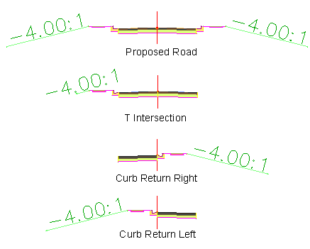
In this exercise, you will create a tool palette, and then save the assemblies that are included in the sample drawing.
Create a tool palette
- Open Assembly-3a.dwg, which is available in the tutorials drawings folder.
This drawing contains an existing ground surface, and centerline alignments and polylines that define a proposed 50-ft right-of-way.
- If the Tool Palette containing the subassemblies is not visible, click Home tab
 Palettes panel
  Tool Palettes
 .
. - In the tool palette, right-click the Tool Palettes control bar. Click Civil Imperial Subassemblies.
- Right-click the Tool Palettes control bar. Click New Palette.
A new tool palette named New Palette is created.
- Replace the New Palette name with Tutorial Assemblies.
Save assemblies to a tool palette
- Zoom in to the assemblies on the right-hand side of the surface.

- On the Proposed Road assembly, select the baseline. Note:
Do not use the grips to drag the baseline marker.
- Click the bottom of the baseline marker. Drag the baseline onto the Tutorial Assemblies tool palette.
The image and name of the assembly are displayed on the tool palette.
- Repeat Steps 2 and 3 for the remaining three assemblies.
- On the Tutorial Assemblies tool palette, right-click an empty area. Click View Options.
- In the View Options dialog box, move the Image Size slider to the right to increase the size of the images on the tool palette. Click OK.
- On the Tutorial Assemblies tool palette, hover the cursor over the Curb Return Left (CR-L) assembly.
Notice that a tooltip is displayed. The tooltip text is automatically generated from the description of the original assembly.
Note:To see the original assembly description, right-click the assembly in Toolspace on the Prospector tab. Select Properties. The description appears in the Assembly Properties dialog box on the Information tab.
To continue this tutorial, go to Exercise 2: Copying Assemblies to a Tool Catalog.