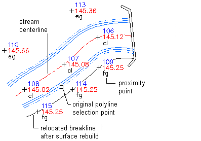
Use the Add Breaklines dialog box to define proximity breaklines that reference surface points in proximity to the vertices of the polyline that you select as the breakline.
Surface points are any surface data points used to create a TIN that are in proximity to the vertices of the polyline that you select as the breakline.
You can define proximity breaklines quickly because you do not have to precisely snap to the surface points that you want to use for the breakline. You can pick locations that are near the points that you want to use. The breakline vertices automatically snap to the nearest surface point when the breakline is added to the surface:

Define proximity breaklines by selecting a polyline or spline. You do not have to draw the original object precisely between surface points. The breakline definition automatically snaps to the surface point that is nearest each object vertex when the breakline is added to the surface.
Proximity breaklines are 2D polylines with elevations of 0. The northing, easting, and elevation are calculated for each vertex according to the closest surface point. By default, proximity breaklines are converted to standard breaklines when added to a surface. You can disable the automatic conversion of proximity breaklines to standard breaklines by setting the Convert Proximity Breaklines To Standard build option to No in the Definition tab of the Surface Properties dialog box.