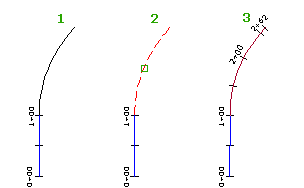
Create a fixed two-point line or three-point curve alignment entity from an AutoCAD line or arc.
The new sub-entity becomes part of the solved alignment geometry if either of the following two conditions are met:
- Before it is converted, it must be attached to an unattached end point of another solved entity in the alignment.
- After it has been converted, it can be joined to the solved alignment geometry using the alignment layout tools.

This command is useful when you must add an AutoCAD line or arc onto an existing alignment.
- Create an alignment or find an existing one.
- Click the alignment. Click


 .
. - On the Alignment Layout Tools toolbar, click
 Convert AutoCAD Line And Arc.
 - Select the AutoCAD entity.
- If necessary, reverse the direction of the alignment sub-entity.
Note: If the sub-entity you converted is hidden behind the source AutoCAD entity, use Shift+spacebar to select it. Hover the cursor over the white AutoCAD entity. Press and hold Shift, then press the spacebar to highlight the alignment sub-entity. Click to select the alignment sub-entity, then release the Shift key. Click the alignment sub-entity again to select it and continue with the command.