The following provides a general workflow for locating and placing content from the Factory Assets library into a factory layout assembly.
- Search for assets in the Assets Browser using the Search option, or manually navigate to components in either the System Assets or User Assets library directories. The Assets Browser is automatically displayed when a new layout is created. To toggle the Assets Browser on and off, click
 Factory tab
 Tools panel
Factory Assets
from the Palettes drop-down menu.
Tools panel
Factory Assets
from the Palettes drop-down menu. - If you are using layers, set current the layer on which you wish the asset to reside.
- Using the appropriate snap type from the Snap Types drop-down menu, place the asset in the factory layout assembly.
- Modify the Occurrence, Model, or Miscellaneous parameter values of the asset, if required.
- Continue to locate and place additional assets, as necessary.
- Use the Reposition command to make minor adjustments to an asset's XYZ placement or angle. Tip: To prevent the Reposition command from launching automatically after placing an asset or inserting a model into your layout, uncheck the Start Reposition command after placing component check box on the Assets tab of the Factory Options dialog box.
Assets Browser system of units
The assets in the System Assets library are available in both the Imperial and Metric system of units. The default system of units is based on the template used to create the factory layout assembly file.
User Assets content is automatically added to the Metric or Imperial directory based on the file units. If an alternate system of units is required, edit the original file, change its units setting, and publish it again.
How to Search for assets in the Assets Browser
You can navigate through the data by selecting folders or you can do a property search.
- In the Assets Browser, enter the asset name or enter a parameter value into the Search field at the top of the browser. When searching on parameter values, the Name, Author, Category, Comments, Company, Keywords, and Title parameters are searched.
- A list of valid search terms is dynamically displayed. You can click one of the terms to populate the search field.
- Click the Search assets button
 to display the asset in the lower section of the Assets Browser.
Once a search is conducted, a Search Results folder is added to the Assets Browser  . The folder contains the asset that was found. The asset remains stored in the folder until the next search is conducted when it is replaced with the new search result. An asset can be selected from the Search Results folder and placed in the factory layout assembly.
How to navigate manually through the Assets Browser
While in the default Thumbnail View, the Assets Browser initially displays the System Assets content in the lower portion of the browser when a file is opened. To return to the top level to access the User Assets content library, click the Folder up button  . From this location, you can double-click folders to move lower or use the Folder up button to move higher in the tree structure.
At the top of the Assets Browser, you can switch to display contents in a Tree View. You can then navigate through the Factory Assets library by expanding directories.
How to sort assets in the Assets Browser
 to display a drop-down menu of sorting options.
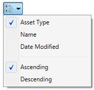
How to locate, preview, delete assets, and identify asset variants
After locating the content you want in the Assets Browser, you can right-click over the asset to display a pop-up context menu. The context menu for a system asset offers three options - Explore, Preview, and Add to Favorites. For cloud-based content, a fourth option called Download Asset appears in the context menu.
Clicking Explore from the context menu opens Windows Explorer and navigates to the Factory Library folder location so you can verify where the asset resides.
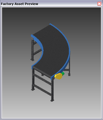
The Preview option launches a separate Factory Asset Preview window displaying the selected asset. You can toggle the Factory Asset Preview window on and off by clicking  Factory tab
Tools panel
Factory Asset Preview
from the Palettes drop-down menu.
Factory tab
Tools panel
Factory Asset Preview
from the Palettes drop-down menu.
The Add to Favorites option lets you add, or remove, frequently placed assets into a Favorites folder for quick and easy access  . An asset can be selected from the Favorites folder and placed in the factory layout assembly
For a published User Asset, the pop-up context menu offers a Delete option. Click Delete if you want to remove the asset from the User Assets library.
A user asset that has been published with variants displays this icon  at the upper left of the asset. The number indicates the number of asset variations. When you right-click over the asset, the Asset Variant option appears in the context menu. Select the variant you wish to place from the Asset Variant submenu. The variations appear with default names like Variant_1, Variant_2, etc., but they can be renamed. For more information, see the Inventor Factory Help topic: Create Asset Variants
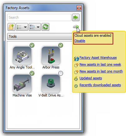
How to enable and disable cloud-based content
Cloud-based content must first be enabled before you can download cloud-based assets. Normally, cloud-based content is enabled by default and this icon appears near the top right of the Assets Browser  .
.
 . To enable cloud-based content, do the following:
 - If you are working in a factory layout, click
Factory tab
Options panel
Factory Options
 to display the Factory Options dialog box.
 - If you are not working in a factory layout, click
Get Started tab
Factory Launch panel
Factory Options
to display the Factory Options dialog box.
- Click the Assets tab and activate the Enable Cloud-based assets check box. Uncheck the box to disable cloud-based content.
- Close the Factory Options dialog box.
How to download cloud-based content
Cloud-based factory assets appear in the Assets Browser using this icon  . When a new cloud-based asset is added, its icon appears like this
  for a period of two weeks. A cloud-based asset must first be downloaded before placing it into the factory layout. To do so, right-click over the asset you wish to place and select Download Asset from the context menu. Once downloaded, the icon assumes this appearance
  .
.
Downloaded assets are stored on your local hard drive in a folder called FactoryCloudLibrary. They are then available for all factory layouts even when you are not connected to the Internet. If a newer, updated version of a downloaded asset becomes available, it appears in the Assets Browser with this icon  .
.
- If you are working in a factory layout, click
Factory tab
Options panel
Factory Options
to display the Factory Options dialog box.
- If you are not working in a factory layout, click
Get Started tab
Factory Launch panel
Factory Options
to display the Factory Options dialog box.
- Click the Assets tab and activate the Disable automatic proxy detection check box.
- Close the Factory Options dialog box.
How to rate and comment on shared cloud-based content
Users can choose to share their cloud-based assets with other users when they publish the asset. When an asset is shareable, other users can rate it or comment on it. The asset ratings and comments are viewable both within the Assets Browser and the Asset Information page of the Web-based Factory Asset Warehouse.
Do the following to rate an asset or create an asset comment:
- In the Assets Browser, click on, or hover your cursor over, the shared cloud asset you wish to rate or comment on. A shareable cloud asset is distinguished from non-shareable assets by the star rating and
Comments
link that appear at the bottom of the pop-up cloud asset information window.
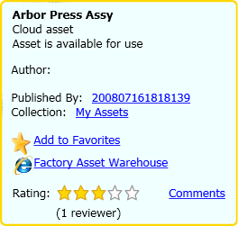
- To provide a rating, simply click the star, 1 through 5, that best represents your opinion of the asset.
- Click the Comments link to open the Asset Comments dialog box. Any existing comments appear within a scrollable window.
- Next, click Add Comment and enter your comment in the Submit Comment field.
- Finally, click the Submit button to add your comment and then click Close to exit the Asset Comments dialog box.
How to place factory assets library components (with published landing surfaces) in factory layout assemblies
System Assets and User Assets content are placed in the factory layout assembly directly from the Assets Browser.
- Locate the asset in the Factory Assets library.
- If you are using layers, set current the layer on which you wish the asset to reside.
- If the component is an asset variant, right-click and select the desired variant from the Asset Variant submenu.
- Press and hold the left mouse button and drag the asset into the factory layout assembly.
- If multiple insertion points have been defined on the model, press the Tab key to cycle through each of the insertion points until you identify the point you want.
- Release the mouse button.
Method 1 - Place independent assets
- Drag the asset to the required location in the assembly and select once using the left mouse button.
- If multiple insertion points have been defined on the model, press the Tab key to cycle through each of the insertion points until you identify the point you want.
- Continue to move the mouse to rotate the asset, or enter an angle in the value input box. Select again using the left mouse button to define the orientation.
Method 2 - Place assets using connectors
Assets that are published with connectors assigned can be used to help locate assets relative to the connectors on other assets.
- Drag the asset so that one of its connectors is within the specified Snap Preview Distance of a connector on the second asset being referenced. The connector points are indicated by green spheres. Once the asset is within the specified Snap Preview Distance, a yellow connector appears indicating a connection can be made.
- Continue to drag closer to the existing asset and once you are within the specified Snap Distance the new asset is snapped into position. Press the left mouse button to confirm placement.
- In the rare event that a connection cannot be made, the connector points change from yellow to red spheres. This can occur if an assembly constraint was created which interferes with the connectors snapping together.
Method 3 - Place assets on grids
Published assets with a predefined landing surface contain a landing surface origin. The landing surface origin is used to locate the asset when it is snapped to the grid.
- Drag the asset to the intersection of two grid lines on the factory floor and select once using the left mouse button.
- If multiple insertion points have been defined on the model, press the Tab key to cycle through each of the insertion points until you identify the point you want.
- Continue to move the mouse to rotate the asset, or enter an angle in the value input box. Select again using the left mouse button to define the orientation.
Method 4 - Place assets on layout sketches
Published assets with a predefined landing surface contain a landing surface origin. The landing surface origin is used to locate the asset when it is snapped to the sketch.
- Drag the asset to a sketch entity on the layout and select once using the left mouse button. Assets can be snapped to endpoints, midpoints, and along an entity.
- If multiple insertion points have been defined on the model, press the Tab key to cycle through each of the insertion points until you identify the point you want.
- Continue to move the mouse to rotate the asset, or enter an angle in the value input box. Select again using the left mouse button to define the orientation.
Method 5- Place assets on DWG overlays
Published assets with a predefined landing surface contain a landing surface origin. The landing surface origin is used to locate the asset when it is snapped to a selected location on a DWG overlay.
- Drag the asset to a 2D drawing entity on the DWG overlay and select once using the left mouse button. Assets can be snapped to endpoints, midpoints, and along an entity.
- If multiple insertion points have been defined on the model, press the Tab key to cycle through each of the insertion points until you identify the point you want.
- Continue to move the mouse to rotate the asset, or enter an angle in the value input box. Select again using the left mouse button to define the orientation.
Continue to place additional instances of the same asset or right-click and select Done from the pop-up context menu to cancel additional asset placement.
Return to the Factory Assets library to locate and place additional assets, as necessary.
You can modify the location and orientation of assets after they are placed by using the commands on the Relationships panel on the Factory tab.
How to place factory assets library components (without published landing surfaces) in factory layout assemblies
User Assets without a defined landing surface are positioned on the factory floor in the same way as unpublished models. For more information, see the Inventor Factory Help topic: Insert models.
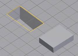
For User Assets content without a defined landing surface, the component is displayed inside a bounding box. The sides of the bounding box are parallel to the component origin planes. The insertion point is the corner of the bounding box that aligns with the origin coordinate system.
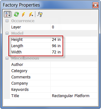
How to modify parameter values in the Factory Properties Browser
Once an asset from the Assets Browser is placed, you can select it and change the available Model parameters or Miscellaneous parameters in the Factory Properties browser. The Factory Properties browser is automatically displayed when a new layout is created. To toggle the Factory Properties browser on and off, click  Factory tab
Tools panel
Factory Properties
from the Palettes drop-down menu.
Factory tab
Tools panel
Factory Properties
from the Palettes drop-down menu.
- In the factory layout, select the asset for which you want to make parameter value changes. (Press and hold the Ctrl key if you wish to select multiple assets.) Once the asset is selected, any of the values displayed in the Factory Properties browser can be edited. Only the Model parameters that were specified as Key parameters when it was published are listed in the Factory Properties browser. A select few iProperty parameters are also listed in the Factory Properties browser. These iProperty parameters include Name, Title, Author, Company, Catalog, Keywords, and Comments.
- Select any of the parameter values in the right-hand column and enter a new value.
- You can restore a changed value by clicking the Refresh button
 .
. - To finalize the change and update the asset, press the Enter key on the keyboard or click the Update button
 . Using the Update button enables you to update multiple parameter values at one time.
 - If you wish to make parameter value changes to multiple instances of the same asset in the factory layout design, click the Update Other Instances button
 .
.
How to modify Asset Variant parameter values in the Factory Properties Browser
Parameter values of a placed asset variant can be modified using the Factory Properties browser.
- In the factory layout, select the asset variant you wish to modify. (Press and hold the Ctrl key if you wish to select multiple assets.) Once the asset is selected, click anywhere within the Selected Variant value field to activate the drop-down arrow at the far right.

Note: Your asset variant parameter name will most likely be different from the example shown in the illustration. - Click the down arrow to display a drop-down list of available asset variant parameters from which to choose.
- Select the desired parameter from the list and press Enter, or click the Update button at the top of the Factory Properties browser.
- The selected asset variant is updated with the new parameter value.
If you wish to provide a different value from any of the existing asset variant parameters, do the following:
- In the factory layout, select the asset variant you wish to modify. (Press and hold the Ctrl key if you wish to select multiple assets.)
- Once the asset is selected, click the Enable Variant Controlled Parameters button
 at the top of the Factory Properties browser to activate the Model Parameter variant name.
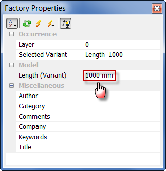
Note: Your asset variant parameter name will most likely be different from the example shown in the illustration. - Enter a new value for the variant parameter name and press Enter, or click the Update button at the top of the Factory Properties browser.
- The selected asset variant is updated with the new value and the word *None* appears in the Selected Variant field.
How do I move a placed asset from one layer to another?
- Select one or more assets from the factory floor layout. Press and hold the Ctrl or Shift keys for multiple selections.
- The layer name of the selected asset appears near the top of the Factory Properties browser. If multiple assets on different layers are selected, the layer name appears as *MultiValues*.
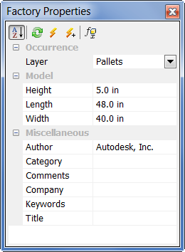
- Click the down arrow to the right of the layer name to display a drop-down list containing the names of all layers defined in the current layout.
- Select the layer you wish to move the selected asset(s) to.
- The drop-down list closes and the layer you selected replaces the previous layer name.
- Click the Update button in the Factory Properties browser toolbar to move the asset(s) to the different layer.
- Press the Esc key, or click an empty area inside the graphics window, to turn off the selection highlighting.
Pits and Platforms
Occasionally, one or more pits of various geometric shapes are required to be set into the factory floor. In other instances, a raised slab, or platform, is also required. Both of these requirements are satisfied using the product-supplied pit and platform system assets.
- Open the Architectural folder in the System Assets browser.
- Next, open the Pit or Platform folders as required.
- Set the appropriate snap-to type from the Snap Types drop-down menu on the Options panel.
- For a pit placement, select the required geometric shape (rectangular, oval, round, etc.) from the Pit folder.
- To modify the dimensions of the asset after placement (including pit solid wall thickness), edit its parameter values in the Factory Properties browser.