A sub-layout of an existing DWG factory layout can be created using the following steps:
- Start by creating a new layout using the New Layout from DWG command. Alternatively, you can start a new layout and add a DWG overlay to it using the Add DWG Overlay command.
- If any 2D Factory assets from AutoCAD exist in the DWG overlay, they are included in the sub-layout. However, any 3D Factory assets placed into the sub-layout are not included.
- Click TOP on the ViewCube to obtain a plan (top) view of the overlay.
-
 On the ribbon, click Factory tab
  Layout panel Create Sub-Layout.
 - The Create Sub-Layout dialog box appears. Provide a name for the new sub-layout and click the OK button.
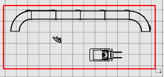
- Next, a window selection set glyph appears in the graphics window. Pick two diagonal corners that fully enclose the objects you want to include in the sub-layout. As you select the corners, a rectangular window appears in red.
-
After picking the second diagonal corner, right-click and select Done from the pop-up context menu.
- The sub-layout opens in a new factory assembly (.iam) window. The name of the DWG overlay also appears as a node in the Assembly browser.
- Save the new sub-layout assembly.
- Return to the original factory layout from which the sub-layout was created. The new sub-layout appears as a sub-assembly node in the Assembly browser with the name with which it was saved.
Note: This restriction includes 3D assets placed with the Auto-place 3D Assets command.
Note: Any sub-layouts within a 3D layout are automatically converted to XREF's (External References) when synced to AutoCAD Factory. If the sub-layout contains any published 3D assets, those assets are replaced with their 2D equivalents in AutoCAD. For more information about the Sync AutoCAD command, see the Inventor Factory Help topic: Suite Workflows.