Sync AutoCAD
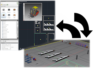
Do the following to create a 2D AutoCAD drawing from a 3D Inventor Factory layout:
- Create a new, or open an existing, layout in Inventor Factory.
 On the ribbon, click Factory tab
  Suite Workflows panel Sync AutoCAD.
 - AutoCAD is started and a 2D drawing of the current 3D layout is created. (AutoCAD Architecture or AutoCAD Mechanical is launched depending on the last version previously opened.)
- In Inventor, a 2D DWG overlay is created and overlaid onto the factory floor.
- In the browser, the DWG overlay node appears with the same name as the original 2D drawing and is represented with this icon
 to indicate the link between the Inventor layout and the newly-created 2D drawing.
Create from AutoCAD
Do the following to create a 3D Inventor Factory layout from an existing AutoCAD 2D factory layout.
 On the ribbon, click Factory tab Suite Workflows panel Create from AutoCAD.
 - The New Layout from DWG dialog box appears. Navigate to and select the AutoCAD 2D layout (.dwg) you wish to use.
- The new Inventor Factory layout is created. Any 2D assets and chainable assets from AutoCAD are automatically populated with their 3D equivalents. Note: Occasionally, non-standard asset lengths are created by AutoCAD Factory in the asset chaining process. These assets are automatically converted to custom assets and represented in the color red. You can disable the custom color, or specify a different custom color, on the DWG tab of the Factory Options dialog box in Inventor Factory.
- In Inventor, a 2D DWG overlay is created and overlaid onto the factory floor.
- In the browser, the DWG overlay node appears with the same name as the original 2D drawing and is represented with this icon to indicate the link between the AutoCAD 2D layout and the newly-created 3D factory layout.
Update from AutoCAD
Use the following procedure to update a 3D factory layout when revisions have been made to the original AutoCAD layout. If the 2D layout is open in AutoCAD, it must first be closed before an update can be performed.
- The browser icon for the drawing node will indicate that the original 2D drawing has been revised
 and the 3D factory layout requires updating.
  On the ribbon, click Factory tab Suite Workflows panel Update from AutoCAD. Note: As an alternative, right-click the drawing node in the browser and select Update from the pop-up context menu.
- The original DWG overlay is deleted and the revised DWG file is once again overlaid onto the factory floor.
- Once the update is complete, the factory layout reflects the revisions from the original 2D drawing.
- In the browser, the DWG overlay node appears with this icon to indicate the link between the AutoCAD 2D layout and the updated 3D factory layout is back in synch.
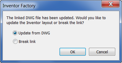
Note: The following dialog box appears when opening an Inventor Factory layout whose linked 2D drawing has been revised. Click OK to update the layout with the changes from the 2D drawing.
Break Link with AutoCAD
Do the following to break the link between a 3D Inventor layout and a 2D AutoCAD drawing.
 On the ribbon, click Factory tab Suite Workflows panel Break Link with AutoCAD. Note: As an alternative, right-click the drawing node in the browser and select Break Link from the pop-up context menu.
- The browser icon for the drawing node resumes its normal appearance
 to indicate the link has been successfully broken.
What if a 3D layout contains sub-layouts?
Any sub-layouts within a 3D layout are automatically converted to XREF's (External References) when synced to AutoCAD Factory. If the sub-layout contains any published 3D assets, those assets are replaced with their 2D equivalents in AutoCAD.
Note: For more information about sub-layouts, see the Inventor Factory Help topic: Create Sub-Layout.