Process of Co-ordinating a "Public Health System"
- Open "Public Health System". Various models have been produced for various applications in the MAP Software Suite, Select accordingly the required for the exercise.
-
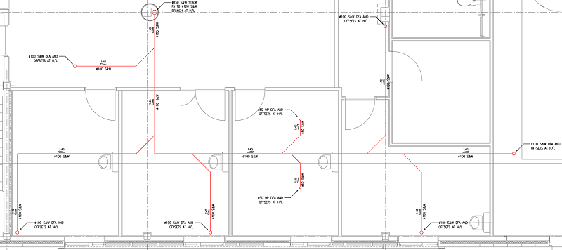
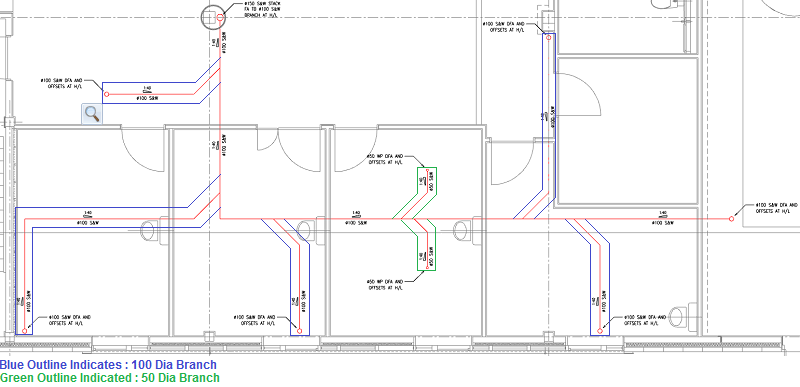
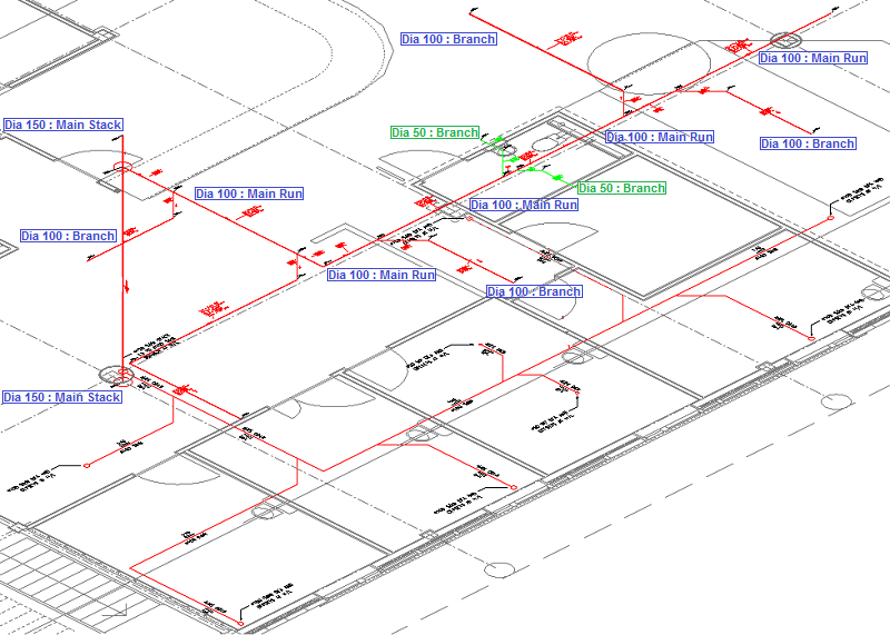
Public Health System Main Stack @ 150.00 Dia
-
Public Health System Main Stack @ 150.00 Dia
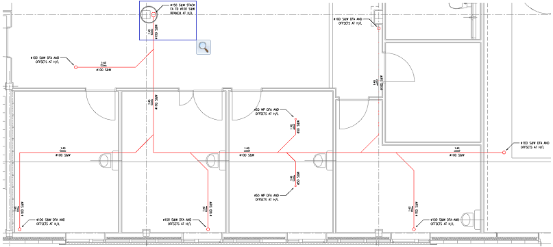
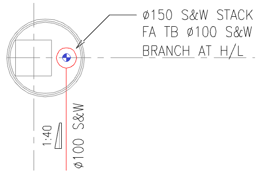
- In the view Zoom into the area of the stack location "Dia 150 S&W Stack FA TB Dia 100 S&W Branch at H/L", as indicated in the upper left area of the building layout.
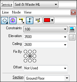
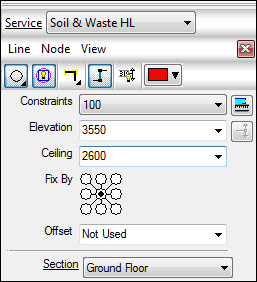
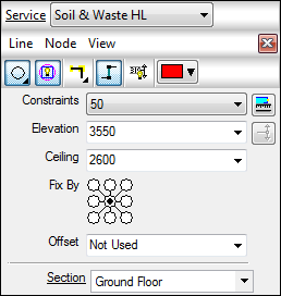
- Select within the "Service Template" drop down menu "Soil & waste HL". The Service template will change accordingly to suite.
- Select
 "New Design Line", the Service Template will adjust accordingly, see below.
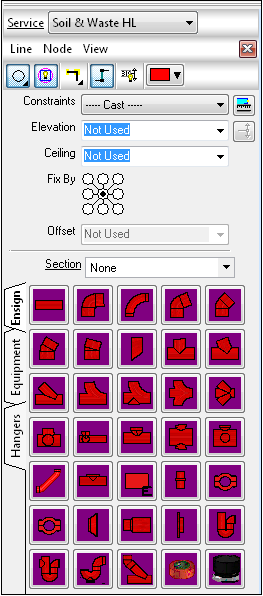
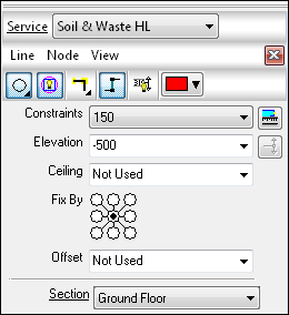
- To create the Main Stack run of the "Public Health System", within the design line dialog, Select from the "Constraints" drop down 150.
- Select "Elevation" type -500. When the Design Line is applied to the Building layout, the first start point will be situated @ -500mm.
- As indicated on the "Fix By" dialog, this dose not need to be changed, with the point set in the central point indicated the "Design Line" will be co-ordinated on the central point of the Fittings.
- Select Section - Ground Floor. Now set, the design line will apply the information of the actual section, to the fittings which are going to be situated within the building layout.
- Select "Line" tab > "Create", with the aid of Snap functionality, select the Center point of the circle indicated on the "Public Health System" layout. The Design line will automatically set to the previous elevation of (-500).
- To set the height of the stack, Within the Design Line dialog, Select "Elevation" type 4150. To automatically set the Design line to the according height, Select

" Add Riser", the Design line will extend to the new elevation @ 90 degrees. To finalize the stack, "Right Click" or select "Enter".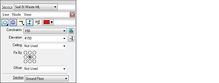
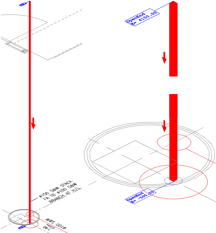
** - MAP Software - Public Health System Main Stack @ 150.0 Dia Design Line - Complete - **
-
Public Health System Main Run @ 100.0 Dia
- In the view Zoom into the area of the stack location "Dia 150 S&W Stack FA TB Dia 100 S&W Branch at H/L", as indicated in the upper left area of the building layout.
- At this stage of the co-ordination, you do not require to Select
"New Design Line", the command is already active. If this is selected the active "Design Line" will change colour from the active "Constraint colour" in this example "Red", to a "Grey shade" indicating an in active system. To re-activate the required "Public Health system", Double select on the line to activate. - To create the Main run of the "Public Health System", within the design line dialog, Select from the "Constraints" drop down 100.
- To set the height of the Main run, Select "Elevation" type (3550).
- As indicated on the "Fix By" dialog, this dose not need to be changed, with the point set in the central point indicated the "Design Line" will be co-ordinated on the central point of the Fittings.
- To set the appropriate ceiling height for each room location, the ceiling dialog must be entered. In this example the ceiling has been made constant from the FFL of (2600.0).
- Select " section - Ground Floor. Now set, the design line will apply the information of the actual section, to the fittings which are going to be situated within the building layout.
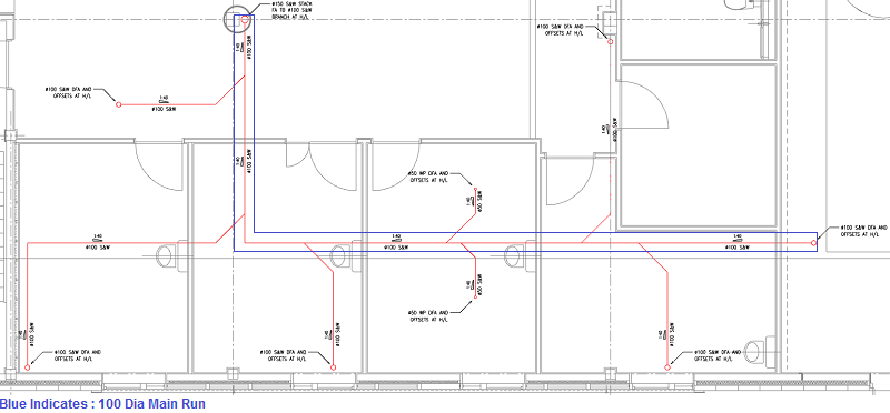
- Select "Line" tab > "Create", with the aid of Snap functionality, select the Center point of the circle indicated on the "Public Health System" layout. The Design line will automatically set to the start point of the design line at the elevation of (3550).
- Co-ordinate the "Design Line" through the building layout, the assistance of snap settings are essential to enable the user to select the appropriate locations on the building layout as indicated below:
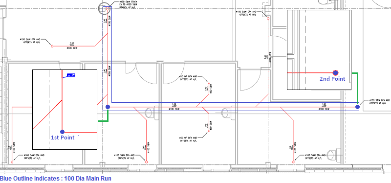
- Select 1st point , with the assistance of snap points.
- Select 2nd point , with the assistance of snap points.
- To finalize the Main Run, "Right Click" or select "Enter".
** - MAP Software - Public Health System Main Run @ 100.0 Dia Design Line - Complete - **
-
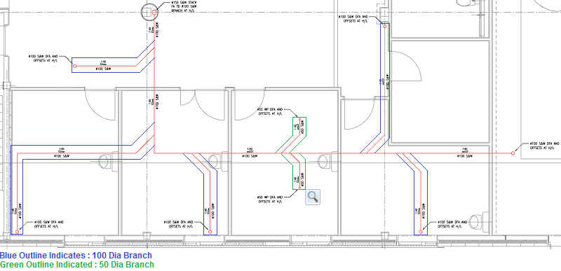
Public Health System Branch Runs @ 100.0 Dia
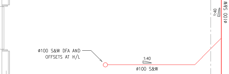
- In the view Zoom into the area of the stack location "Dia 100 S&W DFA AND OFFSETS AT H/L", as indicated in the upper left area of the building layout.
- To create the Dia 100 branch run of the "Public Health System", within the design line dialog, Select from the "Constraints" drop down 100.
- To set the height of the Main run, Select "Elevation" type (3550).
- As indicated on the "Fix By" dialog, this dose not need to be changed, with the point set in the central point indicated the "Design Line" will be co-ordinated on the central point of the Fittings.
- To set the appropriate ceiling height for each room location, the ceiling dialog must be entered. In this example the ceiling has been made constant from the FFL of (2600.0).
- Select " section - Ground Floor. Now set, the design line will apply the information of the actual section, to the fittings which are going to be situated within the building layout.
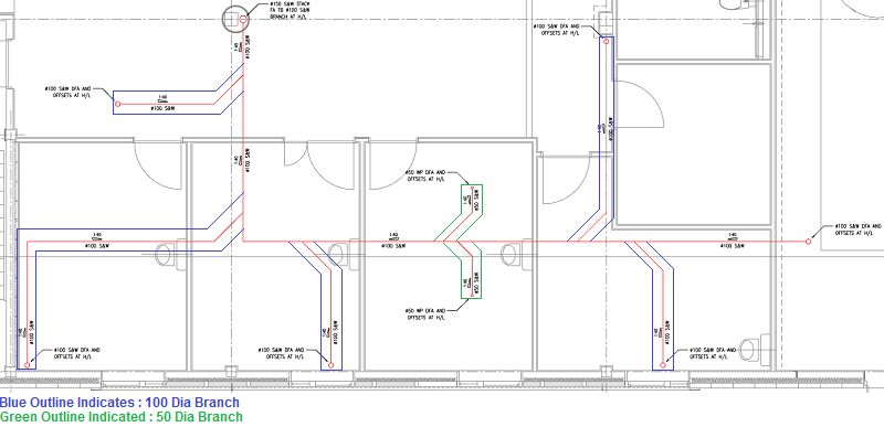
- Select "Line" tab > "Create", with the aid of Snap functionality, select the Center point of the circle indicated on the "Public Health System" layout. The Design line will automatically set to the start point of the design line at the elevation set previously (3550).
- Co-ordinate the "Design Line" through the building layout, the assistance of snap settings are essential, to enable the user to select the appropriate locations on the building layout as indicated below:
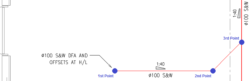
- Select 1st point, with the assistance of snap points.
- Select 2nd point, with the assistance of snap points.
- Select 3rd point, with the assistance of snap points.
- To finalize the "Dia 100 Branch", "Right Click" or select "Enter".
- Repeat the above stages for the outstanding Dia 100 branches, within the "MAP Software - Public Health System" model.
** - MAP Software - Public Health System Branch @ 100.0 Dia Design Line - Complete - **
- Public Health System Branch Runs @ 50.0 Dia
- In the view Zoom into the area of the stack location "Dia 50 WP DFA AND OFFSETS AT H/L", as indicated in the lower right area of the building layout.
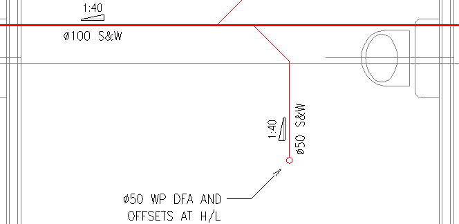
- To create the Dia 50 branch run of the "Public Health System", within the design line dialog, Select from the "Constraints" drop down 50.
- To set the height of the Main run, Select "Elevation" type (3550).
- As indicated on the "Fix By" dialog, this dose not need to be changed, with the point set in the central point indicated the "Design Line" will be co-ordinated on the central point of the Fittings.
- To set the appropriate ceiling height for each room location, the ceiling dialog must be entered. In this example the ceiling has been made constant from the FFL of (2600).
- Select " section - Ground Floor. Now set, the design line will apply the information of the actual section, to the fittings which are going to be situated within the building layout.
- Select "Line" tab > "Create", with the aid of Snap functionality, select the Center point of the circle indicated on the "Public Health System" layout. The Design line will automatically set to the start point of the design line at the elevation set previously (3550).
- Co-ordinate the "Design Line" through the building layout, the assistance of snap settings are essential, to enable the user to select the appropriate locations on the building layout as indicated below:

- Select 1st point, with the assistance of snap points.
- Select 2nd point, with the assistance of snap points.
- Select 3rd point, with the assistance of snap points.
- To finalize the "Dia 50 Branch", "Right Click" or select "Enter".
- Repeat the above stages for the outstanding Dia 50 branches, within the "MAP Software - Public Health System" model.
** - MAP Software - Public Health System Branch @ 100.0 Dia Design Line - Complete - **
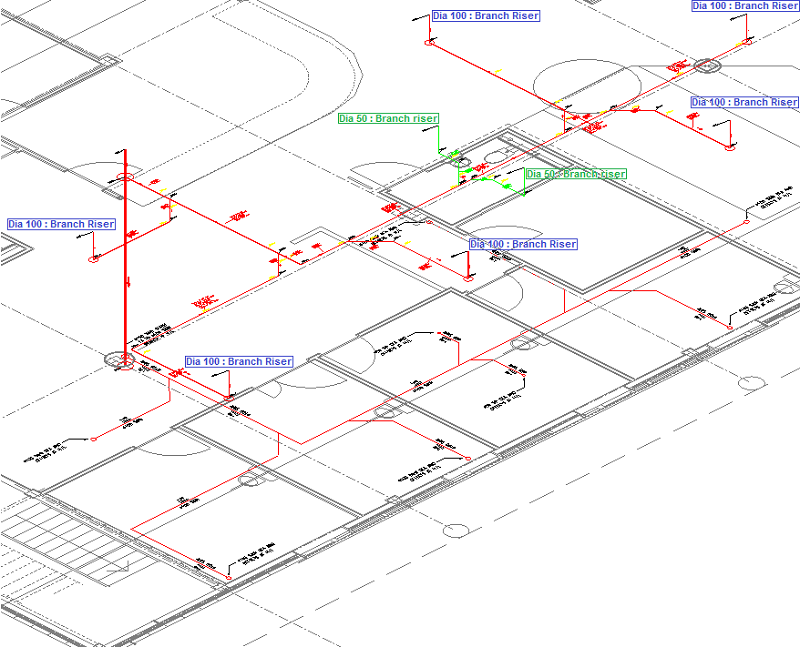
- Public Health System Branch Riser Runs @ 100 Dia
- In the view Zoom into the area of the stack location "Dia 100 S&W DFA AND OFFSETS AT H/L", as indicated in the upper left area of the building layout.
- To create the Dia 100 branch run of the "Public Health System", within the design line dialog, Select from the "Constraints" drop down 100.
- To set the height of the Main run, Select "Elevation" type (4150).
- As indicated on the "Fix By" dialog, this dose not need to be changed, with the point set in the central point indicated the "Design Line" will be co-ordinated on the central point of the Fittings.
- To set the appropriate ceiling height for each room location, the ceiling dialog must be entered. In this example the ceiling has been made constant from the FFL of (2600).
- Select " section - Ground Floor. Now set, the design line will apply the information of the actual section, to the fittings which are going to be situated within the building layout.
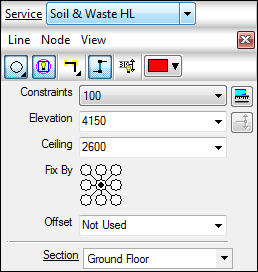
- Select "Line" tab > "Create", with the aid of Snap functionality, select the end point of the line on the "Public Health System" layout, as indicated below:
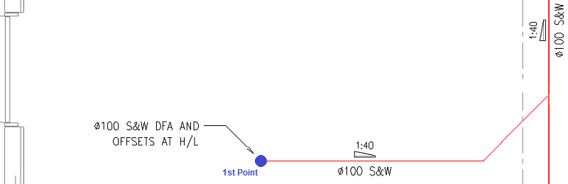
- To automatically set the according height, Select
" Add Riser", the Design line will extend to the new elevation @ 90 degrees. To finalize the branch, "Right Click" or select "Enter". Note: A circle will appear on to the layout, indicating a rise location. - Repeat the above stages for the outstanding Dia 100 branches, within the "MAP Software - Public Health System" model.
** - MAP Software - Public Health System Branch Riser Runs @ 100.0 Dia Design Line - Complete - **
- Public Health System Branch Riser Runs @ 50 Dia
- In the view Zoom into the area of the stack location "Dia 50 WP DFA AND OFFSETS AT H/L", as indicated in the upper left area of the building layout.
- To create the Dia 50 branch run of the "Public Health System", within the design line dialog, Select from the "Constraints" drop down 50.
- To set the height of the Main run, Select "Elevation" type (4150).
- As indicated on the "Fix By" dialog, this dose not need to be changed, with the point set in the central point indicated the "Design Line" will be co-ordinated on the central point of the Fittings.
- To set the appropriate ceiling height for each room location, the ceiling dialog must be entered. In this example the ceiling has been made constant from the FFL of (2600).
- Select " section - Ground Floor. Now set, the design line will apply the information of the actual section, to the fittings which are going to be situated within the building layout.
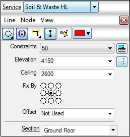
- Select "Line" tab > "Create", with the aid of Snap functionality, select the end point of the line on the "Public Health System" layout, as indicated below:
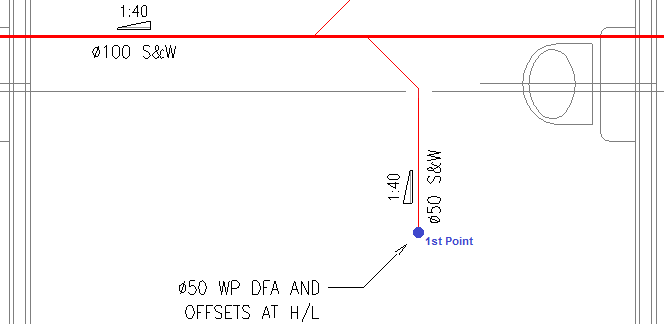
- To automatically set the according height, Select
" Add Riser", the Design line will extend to the new elevation @ 90 degrees. To finalize the branch, "Right Click" or select "Enter". Note: A circle will appear on to the layout, indicating a rise location. - Repeat the above stages for the outstanding Dia 50 branches, within the "MAP Software - Public Health System" model.
** - MAP Software - Public Health System Design Line - Complete - **
Note: The design line co-ordination of the "Public Health System", requires further co-ordination and modification, refer to the following topic, Drainage Tool - Design Line Example within the example, further explanation and step by step guide on how to configure appropriate falls and elevations within the system.