|
The Levels command is used to display the height of the duct from the level (Z=0) or a Datum point set up in the http://beehive.autodesk.com/community/service/rest/cloudhelp/resource/cloudhelpchannel/guidcrossbook/jsonp?v=2015&p=FABRICATION&l=ENU&guid=GUID-ABD77BCF-F9C0-4B5E-872C-C3B97B1B6659 area of the main database. Levels can be displayed with reference to the top of the Duct (T.O.D.) or the bottom of the duct (B.O.D.) or both.
- Select
 Edit Main Database.
 - Scroll down to Level Text options.
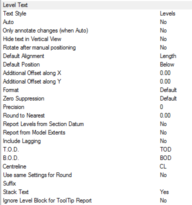
- The Style box is used to specify the AutoCAD Text Style to be used. If the Text Style Levels is not present, then Standard is used by default.
Options
- Text style - Text properties taken from Style named here, if the style dose not exist "Standard" is used. Height, Width, Font etc are defaulted from style. > If only displaying in Paper, Height should be size required for plotting.
- Auto - Automatically applies the Numbers label to each item drawn.
- Only annotate changes (when Auto) - Only applies a Size label, when the item has changed Size or cross section from the previous item connected from > Note : Option Auto must be set to Yes to utilise the Only annotate changes.
- Hide text in Vertical View - Hides stacked annotation in Vertical views, e.g. for a riser viewed in Plan would only display the base items' annotation.
- Rotate after manual positioning - An option to rotate the Size label; useful if the Label alignments option do not allow desired Alignment because of UCS or Item rotation.
- Default Alignment - Sets the annotations' alignment: View, Length or Connector (default Length).
- Default Position - Sets the annotations' alignment: Below, Middle or Above (default Below).
- Additional Offset(s) X, Y - Allows an additional offsets from the default Position.
Format
If the Format option is set to value greater the 1, then the above settings are over-ridden as follows:
- 1 - Scientific 1.55E+01
- 2 - Decimal 15.50
- 3 - Engineering 1'-3.50"
- 4 - Architectural 1'-3 1/2"
- 5 - Fractional 15 1/2"
Zero Suppression
- Default
- Suppresses zero feet and precisely zero inches
- Includes zero feet and precisely zero inches
- Includes zero feet and suppresses zero inches
- Includes zero inches and suppresses zero feet
- Suppresses leading zeros (Decimal)
- Suppresses trailing zeros (Decimal)
- Suppresses leading and trailing zeros (Decimal)
Precision
If set to -1, precision is controlled by the AutoCAD - Format Units setting. If set to 0-7, precision is controlled by CADmep+ (zero to seven decimal places)
- 0
- 0.1
- 0.12
- 0.123
- 0.1234
- 0.12345
- 0.123456
- 0.1234567
- 0.12345678
- Round to Nearest
- Report Levels from Section Datum - Forces the Levels command to use the Elevation Datum value from the http://beehive.autodesk.com/community/service/rest/cloudhelp/resource/cloudhelpchannel/guidcrossbook/jsonp?v=2015&p=FABRICATION&l=ENU&guid=GUID-ABD77BCF-F9C0-4B5E-872C-C3B97B1B6659 as a datum rather than the items physical position in the drawing i.e. Duct located at zero can report a level of 10m
- Report from Model Extents - Levels report from the Items' Model Extents
- Include Lagging - Levels reported include an items external lagging
- T.O.D. - Abbreviation displayed for the Top Of Duct value
- B.O.D. - Abbreviation displayed for the Bottom Of Duct value Note: Leaving the T.O.D. or B.O.D. fields empty will stop any Levels information displaying.
- Centreline - Abbreviation displayed for the Centre Line value (Round only)
- Use same Settings for Round - Forces Round Levels to be taken from the Top/Bottom of duct rather than the default setting (Centre Line)
- Suffix - Option to include a Levels suffix
- Stack Text - Levels text stacks vertically rather than horizontally
- Ignore Level Block for ToolTip Report - Enables or disables the ToolTip reporting as per the Level Block attributes (if in use).
Using the Levels command
- Click the Levels icon
 .
. - Select the Items to displayed the levels. This can be done using any of AutoCAD normal selection commands.
- Right Click to execute the command.
The Levels text should now be displayed. The Levels text can be moved and rotated using the AutoCAD Grips or using the CADmep+ Move Text  and Rotate Text
  commands.
Topic : Custom Level Blocks
Additional Notes:
-
Selecting and reapplying any of the CADmep+ Label commands will toggle the Label on or off.
-
If the Label is toggled off then on again it will remember its original position and rotation.
-
If no Annotation is displayed check that the AutoCAD Text Style has been setup correctly.