CAMduct has the ability to generate output files for many Duct Board systems, this help file will walkthrough setting up of a machine, with a Dual Router configuration, and generating the NC file that the Router controller can read. Topics covered are:
- Machine Setup
- Tool Setup
- Ductboard Settings
Installing the Machine Setup
During the Installation, the Machine Files will have been put into the Database Folder (by default this would be in C:\CAM-Duct\Database\).
This can be verified by going into File - Setup - Installed Machines or by clicking on the Installed Machines Icon in the Utility Bar.
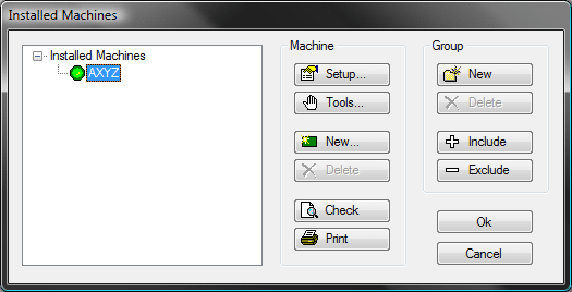
In this example I will be using the Axyz machine but the principles will apply to most machines, any differences will be explained by the machine manufacturer or distributor. If the Router Machine is not visible it can be added to the list by clicking on the Include button. 
This will open the Select Window, the Installed Machine should be in the Drop Down to be included in the list.
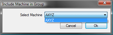
Click OK to accept.
The Installed Machines dialogue is made up of 2 parts, the Machine Setup and the Tools Setup.
Click on the Setup Icon  to get into the Machine Editor.
Machine Editor
The Machine Editor is made up of 7 Tabs that define the settings used by the Installed Machine. The first tab that is visible is the Machine Tab.
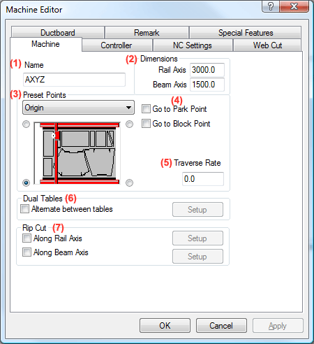
(1) The Name field is where the user can specify a name to Identify the machine in his Installed Machines list. By default this will be the Machine name but this can be changed if desired.
(2) The Dimensions fields are where the physical Table Dimensions are entered. This is defined by the measurement along the Rail Axis, (Length), and the Beam Axis, (Width).
(3) Preset Points. The diagram below is representative of the table bed and has a button in each corner. These are used to determine the key reference points on the table. These are explained below.
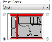
Select a reference point and then click on the required corner.
Origin
This is set to define the machine's x/y axis orientation and, in most cases the x=0, y=0 point. This is machine/controller dependent and after installation should not be altered unless instructed by the software vendor. In the Axyz configuration this is set to the Bottom Left corner of the diagram.
Home Point
This is the position where the software will place the Nested parts if Move Nest to Home Point is selected in the NC Settings tab. In the Axyz Configuration this is set at the Bottom Left.
Start Point
The machine will start to cut a nest from this point. If this is not the same as the Home Point, the tool will make a rapid traverse to the corner of the nest determined by the Start point. In the Axyz Configuration this is the Bottom Left.
Park Point
This defines the position the tool will return to after the parts are cut, provided that the Go to Park Point, (see part (4)), tick box is selected. This allows the user to remove the cut parts and place a new sheet on the bed without the Tool head getting in the way. In the Axyz Configuration this is set to the Top Right.
Block Point
The Block Point is used in Level 1 Installations where NC is written for a single part in the Profiler. The Block Point is a single point on the bounding rectangle of the part, the last line of NC would be a command to move back to the Block Point so the same part could be cut again. If Go to Block Point, (see part (4)), is ticked then the tool will return here after cutting has finished. This is not used in the Router Configuration.
Nesting
Allows the user to specify a Nesting position on the bed that may be different from the Home position. In the Axyz Configuration this would be the Bottom Left.
(4) Go to Park Point / Block Point
If the Go to Park Point tick box is selected, the Tool head will move to the location specified under the Park Point in Preset Points. The Block Point is not used in the most Router Configurations.
(5) Traverse Rate
Enter the speed at which the tool head will move when in rapid traverse (between parts when not cutting) - typically 20,000 mm/minute or 800"/minute, but check with your machine supplier. This value is also used to accurately calculate the time to cut a sheet of parts.
(6) Dual Tables
Some machines can have two cutting tables or are long enough to allow two sheets to be mounted along the length. The software can then be set up to move between tables automatically. This is currently not supported in the Router Configuration.
(7) Rip Cut
Before, or after, cutting a nest, the program can cut off any remaining length or width of the sheet dependent on the settings here. A rip cut is a latitudinal or longitudinal cut that separates unused sheet from the part of the sheet that has been cut upon.
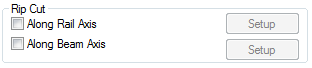
If the Rip Cut is selected there are different ways it can be implemented.
Along Rail Axis
Cuts the sheet along the rail length.
Along Beam Axis
Cuts the sheet along the beam axis.
To specify the type of cut (rail or beam) and the various options, once the appropriate rip cut box is ticked click on Setup. This opens up a new window which enables the following options.
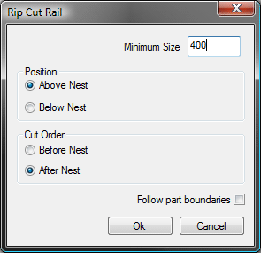
Position
Allows the rip cut to be set either above nest or below nest.
Cut Order
Allows the rip cut to be performed either before or after the rest of the nest has been cut.
Follow part boundaries
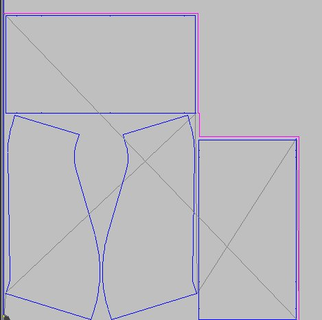
Sets the rip cut to follow the outside of the parts on the nest allowing for the margin between nested parts. The screen-shot below shows how the rip cut follows the part boundaries along the rail axis.
The next tab we come to is the NC Settings Tab.
The NC Settings Tab
This contains options that directly affect the final NC data file output.
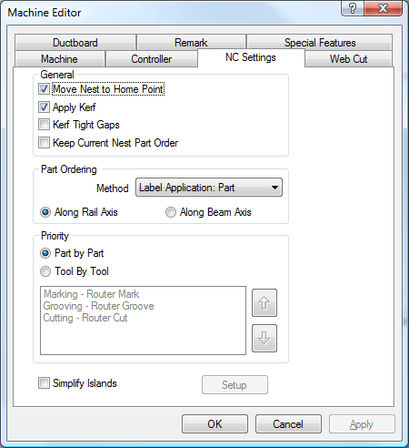
Move Nest to Home Point
This option will adjust the position of the nest to the Home Point specified in the Preset Origins.
Apply Kerf
Applying Kerf within the software will adjust the NC to compensate for Kerf, nullifying the need to adjust it at the controller. This is Ticked in most configurations.
Kerf Tight Gaps
This option will apply kerf to small spaces such as 3mm Vee Notches This is not used or needed in a router configuration.
Keep Current Nest Part Order
If ticked, the Post Processor will not change the cut order, if it has been previously edited on the Nest. This would not normally be needed in the router Configuration as cut orders are normally used for things like Heat Dissipation.
Part Ordering
This option determines the order in which the parts will be cut. If the Keep Current Nest Part Order box is ticked, this option will not be available. The Methods that can be selected are Label Application (i.e. keep the same cutting order as printed with the part labels) , Allow Heat Dissipation (not applicable) and Shortest Path (where the controller will make the decisions based on its own internal settings) . In a router configuration this is kept at Label Application: Part
Along Rail Axis / Along Beam Axis
This determines which axis is to be cleared first.
Priority
These settings determine in what order the machine will use the tools to manufacture the parts.
Part by Part
This option will use multiple tools on the same part before moving on to the next part. If this option is selected it will first cut with the Marking Tool, then the Groove Tool, then go round the same part with the Cutting Tool. This can increase the cutting time if a sheet is full of small items due to the time taken to change the tools.
Tool by Tool
On Axyz machines this will determine the order that tools are used in. Highlight a tool by clicking it, then use Move Up / Move Down arrows to change the tool order. It is recommended that the Tool by Tool option is used on a router machine. The order normally used in the a router configuration would be Grooving, Marking, then Cutting.
Simplify Islands
Simplify takes the drawing and reduces its level of complexity so that when the NC is written for it, there are less instructions to download to the cutting machine. This is not used on router Machines or Ductboard patterns.
The Controller Tab
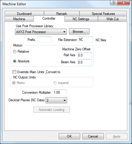
The Controller tab is where the Post Processor is selected along with other parameters that affect the NC that is being written.
In the Router Configuration we set the " Use Post Processor Library" to read the post processor supplied with the software, if this is not displayed, or available in the pull down menu, then click on the Browse button and browse to the location of the post processor file normally in the CAM folder, if this is not available then contact your software supplier.
The default File Extension used by the router controller is automatically placed in the File Extension box, this can be edited if desired.
Most Router Machines use code written in Absolute Mode, ensure that this is selected in the Motion box or changed to Relative if advised by the machine supplier.
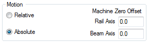
There is no need to enter a Machine Zero Offset.
It is possible to convert the NC to Imperial (if working in Metric) or Metric (if working in Imperial), though this is not usually necessary unless the Main Database is not configured correctly.
For the Axyz Configuration we will be working with the Conversion Multiplier set to 1. If working in Metric we would have the Decimal Places (NC Data) set to 2, in an Imperial setup this will be set to 3.
Automatic Loading, if supported by the Router Machine, will automatically load the nest sheet number in the Job after the first sheet has finished cutting.
The Remark Tab
The Remarks option allows the user to place information into the NC code, this can be useful in reading the code by hand and tracking what is being done.
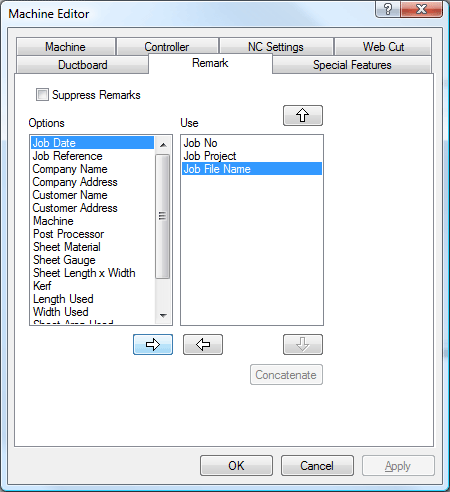
The information that can be displayed is available on the left hand column, this can be moved, and used, by highlighting the object and clicking on the Add arrow  .
.
Adversely, information can be removed from the NC by highlighting it on the right and using the Remove arrow  .
.
There is also the option to Suppress Remarks which will ensure that no extraneous information is written to the code.
The Special Features Tab
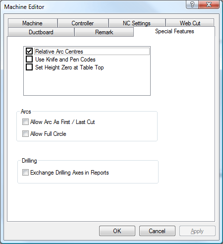
In the Axyz Configuration there are two Special Features that are used and they are the Relative Arc Centres, and the Set Height Zero at Table Top. The Axys Control, while using Absolute Motion, also uses a Relative position for calculating Arcs. This has to be ticked in order for it to work correctly. The Tool position in the Z axis can also use the Table as the Zero point or the top of the Material, this will be dependant on the machine being used the Special Features will be specific to that machine.
The Ductboard Tab
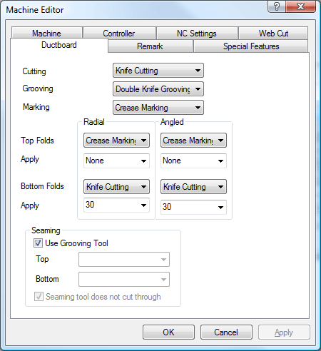
The Duct Board Tab enables the user to customise settings to match the specific Tools and Settings on the required Machine.
The first section determines the tooling and length of any Marking and Fold indicators. This is split into Tool Allocation where the user can define what tools will be used for Cutting, Grooving and Marking. The next section allows the user to define the tools to use for folding.
There are 2 types of fold, Radial (As used on a Radius Bend Back Wrapper) or Angled (as used on a Rectangular Bend Back Wrapper), and whether the fold is on the Top or Bottom of the material.
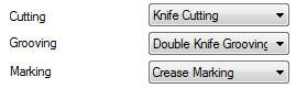
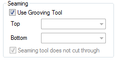
The Seaming Section allows the user to use the Default Grooving Tool to apply the Seam Chamfers or the user can specify what tool, from the available tools in installed machines, to use when Cutting or Marking Seam Edges.
Web Cut Tab
This is not used in the Router Configuration.
Tool Setup
Tool Settings are available from the Installed Machines by clicking on the Tools button. 
It is advised that the Materials that are to be used are setup first by going to File - Setup - Main Database - Materials, or by clicking on the Main Database Icon from the Utility Bar. This is because the Tool Settings will need to be configured to the different thicknesses of DuctBoard material to be used.
Details on entering and configuring Materials are available http://beehive.autodesk.com/community/service/rest/cloudhelp/resource/cloudhelpchannel/guidcrossbook/jsonp?v=2015&p=FABRICATION&l=ENU&guid=GUID-BEADE391-1DA7-4304-BF81-4FFF998DFA06.
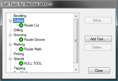
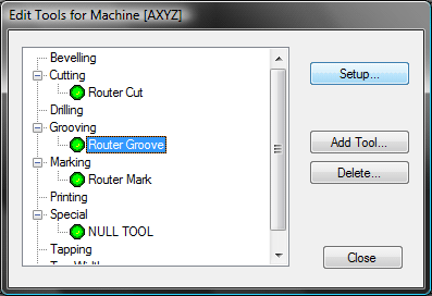
The Edit Tools Dialogue should be setup as above. If there are no Tools in the setup then you will have to add them by clicking on the " Add Tool..." button  .
.
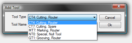
This will display the available Tools that the Router Machine can support. Select the Tools that are required so that the Edit Tools looks similar to the one above.
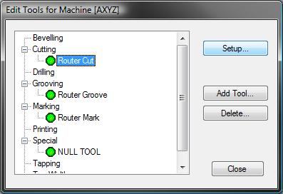
We then have to setup the parameters for each Tool. This is done by clicking on the Tool name and then clicking on the " Setup..." button.
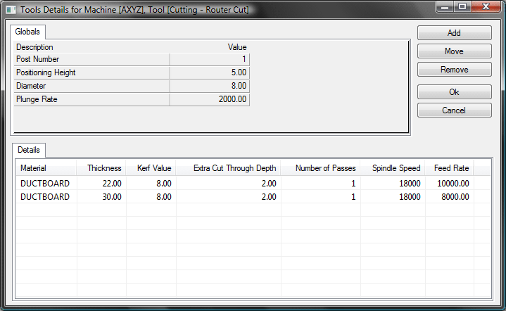
The Tool Details Dialogue contains information on the Tools used by the Cutting Machine. This is split into 2 sections, Global and Details. Settings can be transferred from one to the other by using the Move Button.
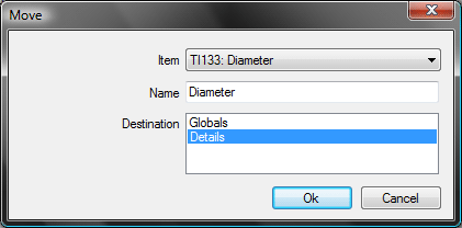
In the above scenario clicking OK would move the Tool Diameter from the Global Settings to the Details.
Global Settings
These settings will be applied globally to this tool regardless of the Material being cut and the Gauge of the Material. In the AXYZ machine setup for the Cutting Tool this would be setup as follows:
Post Number
This is used to identify the Tools used by the router machine, in the above instance, for the Cutting Tool, this would be set to 1.
Positioning Height
The Positioning Height is how far above the board the Tool will move when traversing between cuts.
Diameter
This is the Diameter of the Cutting Tool being used, in this case it is an 8mm Straight Cut Router.
Plunge Rate
This is the speed that the Cutting Tool will descend into the Ductboard Material.
Details
The Tool Details are the parameters that are Material and Thickness specific. The default settings are as follows:
Material
This is the Name of the Material the settings are being applied to, this is automatically added to the Tools Database and will list all materials from the Material Database.
Thickness
This is the Gauge or Thickness of the Material and is added automatically to the Tools Database from the materials listed in the Material Database.
Kerf Value
Kerf is the allowance required to compensate for the tool width. With thermal cutting tools the kerf value is normally material and gauge dependent. If Kerf = 1.0, and you need a Part 100 x 100, then the program will compensate and cut along a centre line at 100.5 x 100.5. When cutting a hole 100 x 100 the centre line would be 99.5 x 99.5. In the AXYZ configuration this would be the Cutting Tool Diameter which in this case is 8mm.
Extra Cut Through Depth
This is the allowance that makes the Cutting Tool cut through the Foil and into the sacrificial MDF Board. This value may be variable but will be around the 1mm - 2mm mark. A couple of test cuts are normally required to find the optimal Extra Cut Through Depth.
Number of Passes
This is the number of times the tool will go round the cut path. This is normally set to 1.
Spindle Speed This is the rotation speed of the cutting tool spindle. This will vary according to the Thickness and Grade of material you are cutting. The default speed is 18000
Feed Rate
The Feed Rate is the speed that the cutting tool will move through the Material, again this will be dependant on the Grade and Thickness of the Material being cut. By default this is set to around 10000 but a number of test cuts may be required to find the optimal cutting speeds.
Click OK to apply these settings and save them to the Cutting Tool Database.
Select the Router Groove Tool from the Edit Tools Dialogue and click on Setup.
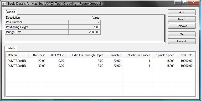
Again this dialogue window displays Global and Details settings.
Global
The following parameters need to be setup in the Global section:
Post Number
This is the identification number used by the machine to identify the Groove Tool.
Positioning Height
The Positioning Height is how far above the board the Tool will move when traversing between cuts.
Plunge Rate
This is the speed that the Cutting Tool will descend into the Material.
Details
The Tool Details are the parameters that are Material and Thickness specific. The default settings are as follows:
Material
This is the Name of the Material the settings are being applied to, this is automatically added to the Tools Database and will list all materials from the Material Database.
Thickness
This is the Gauge or Thickness of the Material and is added automatically to the Tools Database from the materials listed in the Material Database.
Extra Cut Through Depth
For the Groove Tool we do not want it to cut through the foil so this value will be a negative number. It is advisable to do a number of Test Cuts to set this value, it is set by default to -3.
Number of Passes
This is the number of times the tool will go round the cut path. This is set to 1.
Spindle Speed
This is the rotation speed of the cutting tool spindle. This will vary according to the Thickness and Grade of material you are cutting. The default speed is 18000.
Feed Rate
The Feed Rate is the speed that the cutting tool will move through the Material, again this will be dependant on the Grade and Thickness of the Material being cut. By default this is set to around 10000 but a number of test cuts may be required to find the optimal cutting speeds.
Click OK to apply these settings and save them to the Cutting Tool Database.
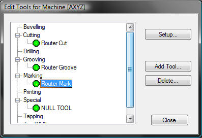
Next we will set up the Router Marking Tool.
When making Patterns such as Square Bends or Mitred Offsets it is not possible to cut the Groove on the Underside of the Ductboard Material as all Developments are cut with the inside of the Duct uppermost. An example of this is in the Square Bend Throat. To get round this we place a Mark where the Groove or fold will have to be made manually. The Router Mark Tool does not use Details so all settings are Global as follows:
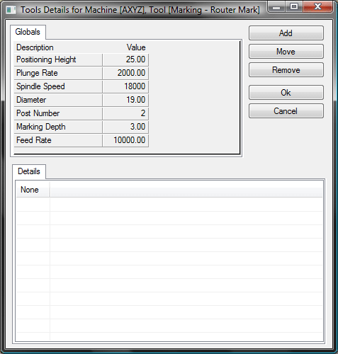
Positioning Height
The Positioning Height is how far above the board the Tool will move when traversing between cuts.
Plunge Rate
This is the speed that the Cutting Tool will descend into the Material.
Spindle Speed
This is the rotation speed of the cutting tool spindle. This will vary according to the Thickness and Grade of material you are cutting.
Diameter
This is the Diameter of the Tool being Used to do the Marking.
Post Number
This is the identification number used by the machine to identify the Tool being used for Marking.
Marking Depth
This is how far into the Material the tool will go to make the Mark.
Feed Rate
This is the speed that the tool will use to make the Mark.
Click OK to Accept the changes.
The last Tool is the Null Tool which is used by the program and does not need any settings.
Click Close then OK to come out of the Machine Database.
Once the Machine has been setup we then have to define the parameters within the Pattern Database > Pattern Options > DuctBoard.

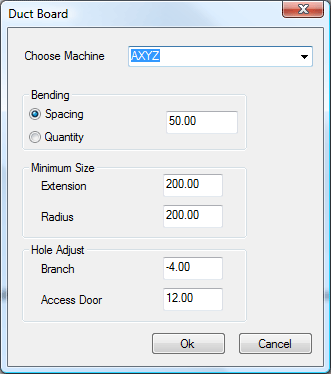
A number of systems have come in that utilise different cutting and marking techniques for creating Duct from this Material. In order to satisfy the requirements of these Machines we have incorporated a Duct Board section into the Pattern Database.
The Duct Board Database enables the user to customise settings to match the specific Tools and Settings on the required Machine.
Choose Machine
This will list the available machines setup on your system, it takes this information from the Machine Database along with any relevant Tools that have been applied.
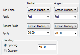
The next section determines the tooling and length of any Marking and Fold indicators. This is split into the type of fold, Radial (As used on a Radius Bend Back Wrapper) or Angled (as used on a Rectangular Bend Back Wrapper), and whether the fold is on the Top or Bottom of the material.
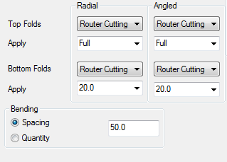
The Bending section allows the user to determine how many fold lines to place on a Radial Fold, or what spacing to use on the Radial Fold.
The Seaming Section allows the user to use the Default Grooving Tool to apply the Seam Chamfers or the user can specify what tool, from the available tools in installed machines, to use when Cutting or Marking Seam Edges.