Each Item drawn in CADmep has a connector to which the next Item will attach. The connectors in CADmep can be made to follow rules that allow or prevent them from being attached to other incompatible connectors. This is referred to as Connector Matching.
Each connector setup in the database can be assigned a type which controls what it is allowed to connect to. These types are as follows:
- Male - Will attach only to a Female connector
- Female - Will attach only to a male connector
- None - Will attach to any connector
- Strict (Match all relevant parameters) - Will only attach to an Identical connector
The connector database is also broken down into groups. When an Item is attached to another Item the Connector Matching feature will check to see if the connectors from each Item are of a suitable type and belong to the same group. If the rules are obeyed the Item is added without any prompting for user intervention. If the rules are broken the Connector Match dialogue is displayed as shown below.
Connectivity rules
The basic rules for allowing interconnectivity is End Type: Male >< Female, for End Type None we only check for the same Group. Beyond these rules, any connector can connect without a miss-match prompt, if the connectors Connectivity column has the same name.
For the coupling patterns (generally CID's 522, 1522, 2522), when configured as an adapter e.g. for a copper to carbon steel service, edit the coupling pattern > Other tab > Connectivity - set the corresponding materials.
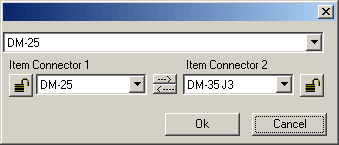
The connector match dialogue allows the user to select the required connector manually. The dialogue is broken down into three specific sections as follows:
- Top pull down menu - This menu displays a list of all the available connectors from the database. Selecting a connector from this menu will change the both Item Connector 1 and Item Connector 2 fields
- Item Connector 1 - Displays the selected connector of the Item currently being attached
- Item Connector 2 - Displays the connector of the Item on the drawing to which the new Item is being attached
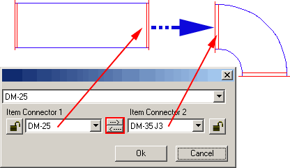
The two small arrow buttons between Item Connector 1 and Item Connector 2 enable the user to pass across the connector information from one connector selection box to the other i.e. If Item Connector 1 is correct and Item Connector 2 needs to match it clicking the arrow pointing to the right will change the information in the Item Connector 2 box to be the same as Item Connector 1 and vice versa. Alternatively the user may select another connector from the drop down menu.