This example will run through how to use Constraint entry for Design. This means that by using pre-defined constraints on velocity, the software can calculate the size of duct required to produce the end flow rate specified at terminals.
- This example uses the default General Supply service which comes with pre-defined line constraints.
- Select New Design line
 .
. 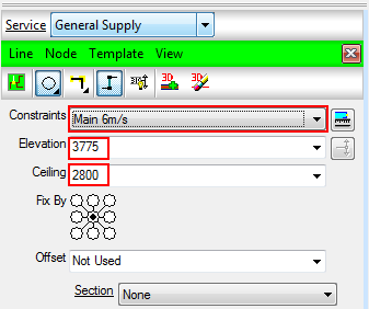
- From the Constraints drop down menu, select which Velocity of line to draw with.
- Type the elevation the line is to be drawn at and the ceiling height of the terminals being placed.
- If using Flat sided ductwork, specify the Fix By position (discussed in more detail in Design Line Takeoff topic.)
- Notice that the command line is prompting to Select Start point. Left clicking the first point on the drawing will then ask for the next point. Using the Ortho option from the toolbar
 or the AutoCAD ortho option, you can specify the distance wanting to be drawn by pointing the line in that direction and then typing in a value to move in millimeters. ENTER key to confirm.
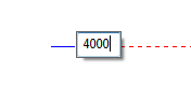
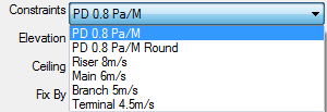
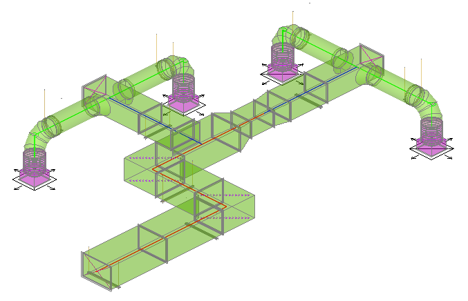
- Begin to draw using the Main 6m/s constraint to draw the main run of ductwork as detailed by the corresponding colors below. Then using the Branch 5m/s constraint for subsequent sub branches. Finally drawing terminal constraint lines using the Terminal 4.5m/s drop down constraint option.
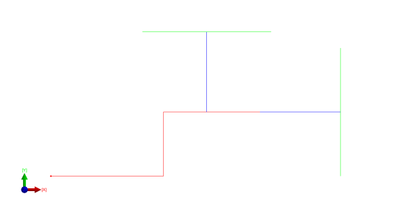
On drawing branches from the main run, Right Click to end a line selection and then select the new constraint from the drop down. Using Nearest snapping options, you can draw away from the main run to draw the branches and terminal lines knowing that they are connected.
- Right click twice to complete the line drawing mode.
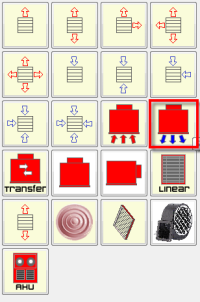
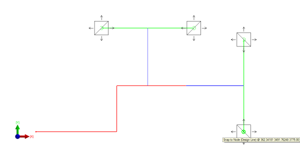
- Now place the terminals onto the drawing. Select the End of Line Equipment tab, and left click on the Supply Terminal button as outlined below. Whilst the design line is activated, Left click where the terminals are to be placed, further left clicks place additional terminals each click. You can use the Snap to Node option to ensure connected to line centrally.
- From the Node
 Terminals dialogue, we are able to specify the Flow rate of each terminal.
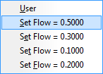
 - Highlight all terminals and then access the Right Click menu Flow settings.
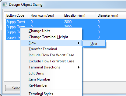
- Selecting Flow User to define a new flow or selecting existing flows that appear after new ones are created.
The Flow has now been saved to the terminals selected and will detail the information from the Terminals dialogue.
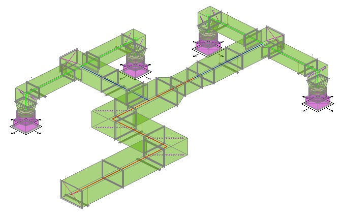
- Click the Fill in 3D button from the Design Line Takeoff menu
 or can be accessed from View
Fill in 3D. - Examine the model to see if the constraint sizes and shape used have been filled correctly.
Changing Constraints
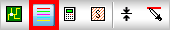
- As shown in the above model, there maybe a need to change the shape of a constraint. This is done by accessing the Manage Constraints dialogue.
- From the Constraints Manager, you can edit the properties of the constrains used in the active Design Line.
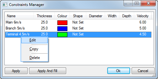
- Right Click on the Terminal constraint and click Edit.
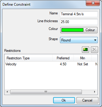
- Change the default shape of the Constraint to Round.
- We are also able to change the default Width and Depth of the Terminal boxes from the Node
Terminals dialogue. Select all Terminals by highlighting the required terminals to be changed and then Right Click Edit Dims, entering a new Carry Width / Depth. - Further adjustments to the Flow rate on the terminals (Node Terminals Right Click Flow after selection) automatically adjusts the duct dimensions to suite when filled in 3D.

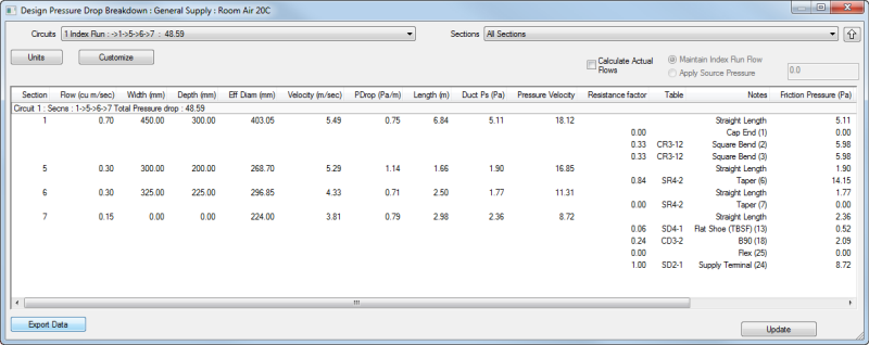
Accessing Pressure Drop Calculations
- Users are able to examine results using the View Calculate Pressure Drop option from the Design Line View menu.
This shows the Design Line calculations of Pressure which can be exported into Excel using the Export Data option from this dialogue.