This topic covers how to use Design Line and the various options that are available at Takeoff. The Design Line menu system has a number of toolbar options and drop down menus in itself. The Line, Node and View menu help can be found within the Design Line Toolbar and Menus.
There are 2 methods Design Line Takeoff, Size Entry or by Constraint based entry. This topic will primarily cover Sized based entry. For further information on Constraint based entry, please read the Design Line Constraint Entry.
Once the Design Line option is selected using the main toolbar icon 
, The Design Line Takeoff menu is ready for entry and is awaiting Size or Constraint selection.
For Size Entry
Size Entry is enabled from within the selected service and can be enabled/disabled from Service Link  Design Entry tab Enter by Size option. Disabling this option will resort in Constraints entry being the default for this service. This can additionally be accessed from the Design Line Toolbar and Menus.
 Line Creation: Initiates the command to start a new line inside of the existing Design Line. Prompts for Select Start Point and awaits Left click of first point to start drawing. Line creation causes the Menu to hightlight green as shown in this example. Please note: Selecting the Toolbar icon from the 3D viewer or CADmep toolbar will start a new Design line and deactivate the current one selected. Only the Line Creation button
should be used to continue working in the same active Design Line.

Shape: As a size is entered, dependant on whether one dimension is entered or two, this will switch between rectangular and round line shapes. For Oval, two dimensions need to be entered and then the drop down for Oval needs selecting.
 Change Shape Automatically : When this option is enabled, this will default the Shape of the Design Line to Round or Rectangular based on the number of dimensions entered. Entering 1 dimension for Round and 2 for Rectangular. The drop don can be used to specify Oval as an alternative.
 Line Mode : Can change the line to be Flexible or to use the default Straight mode. Flexible is used only when required to arc around the node points for flexible pipe or duct. The default is Straight mode.
 Auto Vertical : Setting to move automatically in 90 degree when specifying elevation changes.
 Auto Update Line Position: Used for offsetting Design Lines automatically (Fix By) which can be enabled or disabled when in draw mode. When enabled, the software can calculate a Flat Left movement to Flat Right based on the size entered automatically. Please see Offset Lines - Automatic Method further down in this topic.

3D Fill: Fills the active Design Line with 3D objects. Items are then placed into the job once the visual object appear. For more information on how this occurs, please refer to our Design Line Button Mappings and Button Codes topics.

Erase 3D objects: Clears the active Design line of 3D objects. (Removes them from the job too).
 Design Line colour: Allows selection of colour when drawing the Design Lines. Each design line can be allocated a colour by selecting the drop down arrow for assignment and labelling purposes.
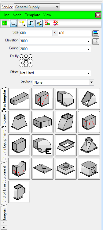
Size: Entry field for application to the Design Line. One dimension entered will automatically draw Round, Two dimension will be treated as either Rectangular (default) or Oval via the Shape selection field of the toolbar. OR Constraint: Lists the available constraints applied to the selected service. Constraints are used as a drop down which determine the size of the line used either flow speed or velocity. There are instances on Pipework where the constraints are used for diameter selection. See more about Constraints in the Design Line Constraint Entry.
Elevation: The height at which the Design Line will be draw at in the model. Use Fix By to determine line position in relation to the object being drawn. When drawing elevations manually (i.e. not using the Add Riser button  ), ensure the Elevation field is set to Not Set else the line will draw to the specified elevation each time.
Ceiling: The height at which Terminals are to default to when placed onto the Design Line. Use Design Line Terminal Styles for preferences of how they are treated.

Pick Length: When specifying a reduction to the line or shape change, after dimensions are entered for the reduction, you are able to select the Pick Length button and use the underlay or reference point on the drawing to dictate the length required.
Add Riser / Elevation change: Use the Add riser option to specify a vertical movement. Entering a new elevation and then selecting this option will draw a line to the new elevation. Holding the Add Riser button down, allows selection of an alternative angle for how to reach the elevation specified. Defaults are 90 degrees.
 Fix By: The User is able to preference where the line is to be positioned in relation to the Fill. The User is able to takeoff Design Lines with the position of Fix By radio buttons (Flat Right, Flat Top or Central alignments). Users can shift the line from one state to the other using the following technique.
Offset Lines
Automatic Method
When Auto Update Line Position
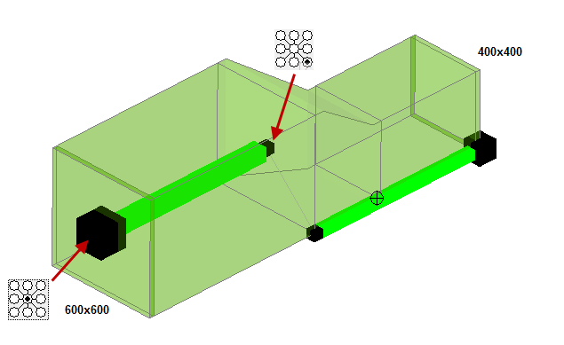
is enabled. Using the Fix By setting will automatically draw a small line to the Fix by position automatically. As a user, you are able just to specify the new Fix By position and let the software dictate where the line position will be. The example below shows a Center line movement to Flat Bottom.
- Starting in 600x600 duct and moving to the position where the offset is required.
- Selecting the new Fix By position when the is enabled will shift the Design Line to the new position.
- Type in the reducing size and then continue to draw in the new Fix By position (Flat Bottom Right).
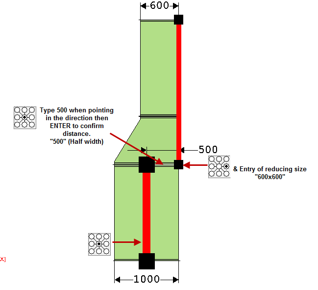
Manual Method
The example below shows a 1000x1000 Rectangular duct tapering to 600x600 keeping the Right side of the duct "Flat Right". The User at the time of changing the Fix By position can point the design line in the required direction and then type half the width (500) in Line Create mode. Pressing Enter to confirm the length required, then at the required Flat Right position, select the Fix by from Central to Right as shown in the diagram below. Together with the reduction in size using the dimension fields will allow you to draw the line Flat Right. Once Filled in 3D, the Alignment should show that the Duct is Straight on the Right side.