Templates can be used for timesaving techniques where a number of products are required to be filled together. These typical arrangements can be stored for future use when using Design Line technology. The following examples show the configuration required in order to create dynamic Design Line Template.
For standardisation, we are able to create Template designs that are used consistently throughout the drawing or tracing of the underlay.
Example: End of Line Terminal
Level: Intermediate
Service: HVAC Supply
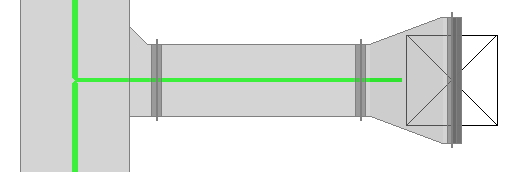
Description: This example shows time saving techniques when drawing multiple branch runs that are identical. Branch Shoe, Rectangular Straight, Taper and Supply Grille.
After drawing the first of many similar scenarios of Design Lines, we are able to create a template.
Once the Design Line with components is ready for saving (This can additionally contain equipment items attached onto the line), select the Template menu option and then click Save.

Select where on the design Line, the insertion point is to be used. This will allow selection of the Design Line in which the user must select the insertion point to be saved for when inserting.
Using the Save dialogue, provide a name for referencing what's on the Design line Template. "Supply Branch". Click OK and template has now been saved for later use.
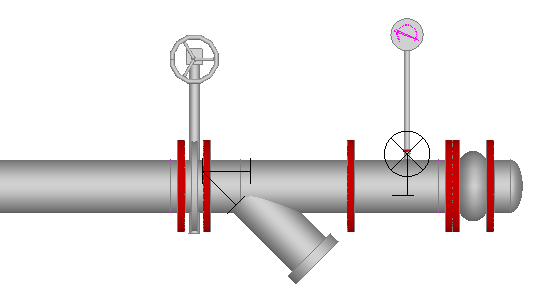
Example: Pump Connection
Level: Advanced
Service: LTHW Flow
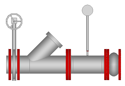
Description: This example consists of an Isolating Valve, Strainer, Pressure Test Gauge with Threaded Reducing Stab In, and a Flex Connection all with PN16 flange connectivity in 150mm Steel.
From within the 3D viewer, Selecting the items from the service allows entry of the objects using the attacher arrow. Add each item to the 3D viewer in the order of the requirement similar to the above. (Manual takeoff of items).
Tip: Draw a length of pipe and use Takeoff as Cut in for each of the inline equipment items.
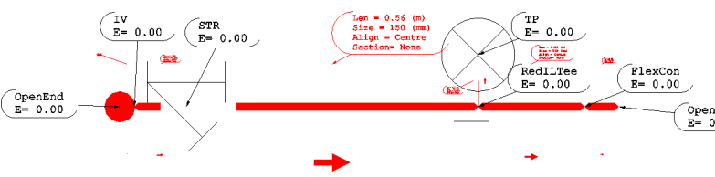
Using the command REVDESIGN, this can convert the objects into a single Design line run.
Select all the components that were drawn with the attacher and then Type REVDESIGN into the 3D Viewer.
When prompted, click where the Source of where the flow is to be placed.
The software will attempt to convert the objects into small design line run.
Verify that the objects have been converted successfully by removing the 3D objects and then double clicking the Design Line to make active, select Fill in 3D . Using button placement, add any additional objects onto the design line ensuring they have a.) the correct size available and b.) a valid button code for filling.
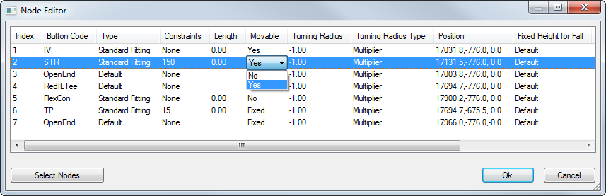
The placement of the nodes may cause overlap when the item is filled in 3D. Whilst the Design Line is active, select Node > Terminals which details the properties of each node placed onto the active line.
In order for nodes to be automatically re-positioned, we can class them as Moveable Nodes. Selecting the components required in this example the valves, and setting the Drop down field for Moveable to Yes. On re-calculation and re-fill, the valves will automatically re-position.
Storing and Using the Design Line Template
Once the Design Line with components is ready for saving and is loaded with Equipment nodes, select the Template menu option and then click Save.
Select where on the design Line, the insertion point is to be used. This will allow selection of the template line for picking an insertion point for where to position during the takeoff process.
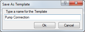
Provide a name for referencing what's on the Design line Template. "Pump Connection". Click OK and the template has now been saved for later use.

When drawing a Design Line and there is a requirement to use the Template previously stored and saved. At the point of insertion select Template > Insert from the Design Line menu options.

The dialogue for selecting the Template will now be presented.
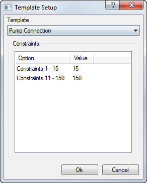
From the Template Drop down, select the previously stored template wanting to be used for the insertion. In this example, "Pump Connection".
Constraints of the lines contained within the Template are listed and are available for changing. The drop down values will contain the Design Line constraints the line was originally using.
Once happy with the selection, Click OK to confirm.
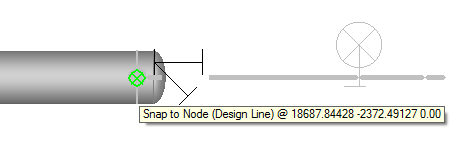
Multiple selection from the insertion point can be achieved. If having a Template that is to be used multiple times, there is no need to Insert each time, Continuous Left clicking on where the insertion points needs to be will apply the Template to that Design Line. Right Click to end the command.
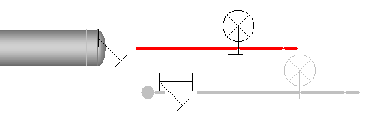
Using the Fill In 3D Button, you are able to view you resulting fill.
This example of a Flow Pump Connection is now ready for the Pump placement which in turn would override the Cap Ends that Dynamic Fill introduces as you draw. We are then able to create a similar Template for the other side of the Pump, Flex Connection, Test point, Non-Return Valve for example.
Storing both these template allows quick access to the arrangement at takeoff saving time in the long run and keeping consistency on spacings, product used etc.
Template can be used on most common scenarios not just the example above. Storing and managing the templates for each drawing.