|
Blocks with attribute definitions can be used to create custom Level \ Size Labels:
- attributes for Levels for reference to the Top, Centre or Bottom of Objects
- attributes for Size for Object Width, Depth & Diameter
Attribute definitions
Cad-Duct/CAD-Mech supports the following attribute definitions
Level attributes
| Attribute Definition: | Levels from: | Object Reference: |
| TOP | Absolute Zero | Top |
| MID | Absolute Zero | Centre |
| BTM | Absolute Zero | Bottom |
| STOP | Soffit | Top |
| SMID | Soffit | Centre |
| SBTM | Soffit | Bottom |
| FTOP | Elevation Datum (Finished Floor Level) | Top |
| FMID | Elevation Datum (Finished Floor Level) | Centre |
| FBTM | Elevation Datum (Finished Floor Level) | Bottom |
Size attributes
| Atribute Definition: |
| WIDTH |
| DEPTH |
| DIA |
Example - Duct work - Reporting Levels from Soffit & Absolute to Bottom of Duct
Creating Attribute Definitions
- Type ATTDEF at the command line.
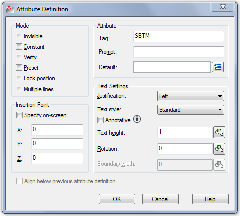
- Type SBTM as the first Attribute Tag.
- The recommendation is that the Text Style height is set to a value of 1 as this is eventually scaled by the Level - Text Style height value. Note: If the Text Style Height field is greyed out, this indicates that the Text Style being used already has a height pre-assigned (Tools > Format > Text Style).
- Click Ok to add the Attribute Definition to the drawing (unless specified will located @ 0,0,0).
- Locate the Attribute Definition - Copy the SBTM definition to create the second Attribute Definition below the first, then use the DDEDIT command to rename the Attribute to BTM, as shown below:
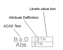
- Use the BLOCK command to create a Block Definition, select the ACAD Text, Attribute Definitions & Level value box. Note: Level Blocks should be created on ACAD - Layer 0, by doing this they inherit the currently selected layer properties (this also allows the text layer to be frozen independently from the 3D duct layer - may require a REGEN).
- Enter a Block Definition Name e.g. "Soffit_Absolute"
- Click Ok to the Block definition dialogue.
Assigning the Block Definition to the Service - Service Type
- Select the correct Service from drop-down menu e.g. HVAC - General Supply
- Select the correct
Service Type
and assign the Block Definition created earlier, as show below:
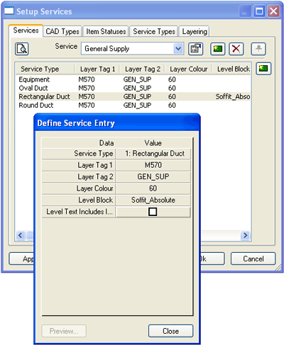
- Click Close.
- Click Apply/Ok to the Setup Services dialogue.
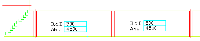
Adding the Block Levels Label
- Add a Rectangular Duct Item to the drawing.
- Select the Levels button
 .
. - Select the Rectangular Duct Item.
Example Pipe work - Reporting Levels from Elevation Datum (Finished Floor Level) to Centre Line
Creating Attribute Definitions
- Type ATTDEF.

- Type FMID as the first Attribute Tag.
- Check that the Text Style height is set to a value of 1.
- Click Ok to add the Attribute Definition to the drawing (unless specified located @ 0,0,0).
- Create ACAD Text for the Level description, as per Example below "CL" - if desired create a Levels' value box.
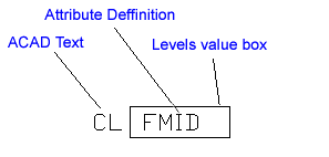
- Use the BLOCK command to create a Block Definition, select the ACAD Text, Attribute Definition & Level value box.
- Enter a Block Definition Name e.g. "Elevation_CL".
- Click Ok to the Block definition dialogue. Note: When setting Soffit or Elevation datum's refer to the Sections topic.
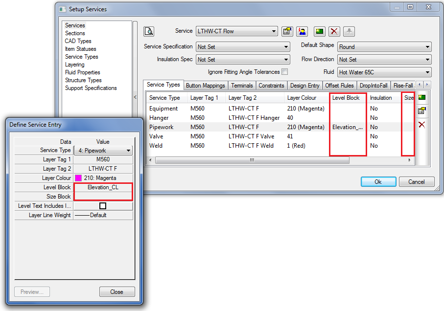
Assigning the Block Definition to the Service - Service Type
- Select the correct Service from drop-down menu e.g. Water & Liquid Supplies - Mains Cold Water
- Select the correct
Service Type
and assign the Block Definition created earlier, as show below:
- Click Close.
- Click Apply/Ok to the Setup Services dialogue.
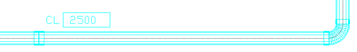
Adding the Block Level Label
- Add a Pipe work Item to the drawing.
- Select the Levels button

. - Select the Pipe work Item.
Example - Steel work - Levels from Absolute to Top of Steel work
Creating Attribute Definitions
- Type ATTDEF.
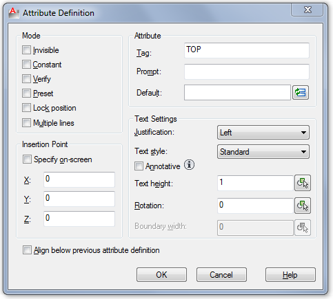
- Type TOP as the Attribute Tag.
- Check that the Text Style height is set to a value of 1.
- Click Ok to add the Attribute Definition to the drawing (unless specified located @ 0,0,0).
- Create ACAD Text for the Level description, as per Example below "T.o.S" - if desired create a Levels' value box.
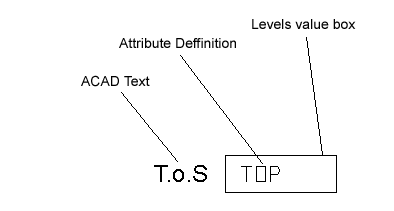
- Use the BLOCK command to create a Block Definition, select the ACAD Text, Attribute Definition & Level value box.
- Enter a Block Definition Name e.g. "Top of Steel".
- Click Ok to the Block definition dialogue.
- Click Ok to the Edit Attributes dialogue. Note: When setting Soffit or Elevation datum's refer to the Sections topic.
Assigning the Block Definition to the Service - Service Type
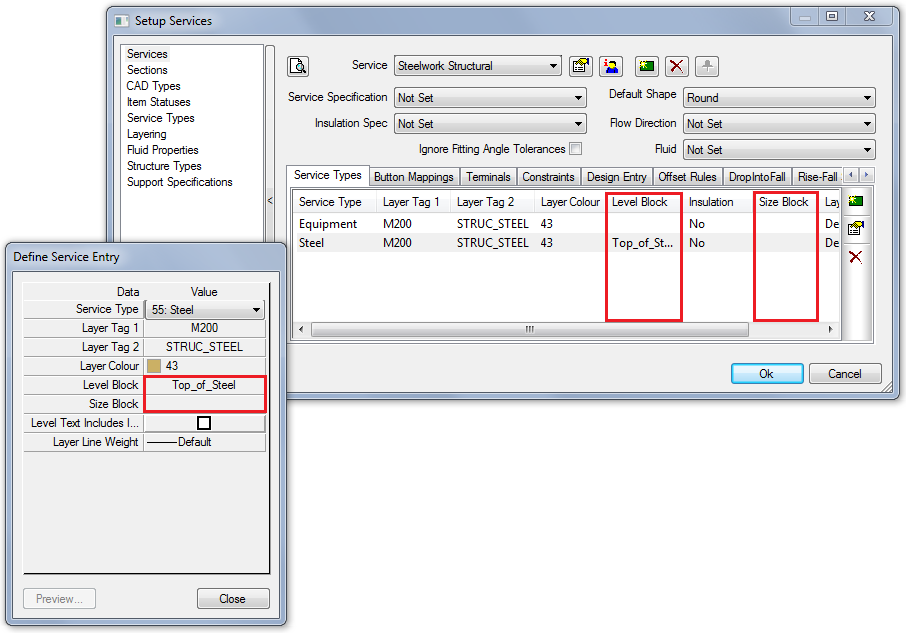
- Select the correct Service from drop-down menu e.g. Structural - Steelwork Structural
- Select the correct
Service Type
and assign the Block Definition created earlier, as show below:
- Click Close.
- Click Apply/Ok to the Setup Services dialogue.
Adding the Block Level Label
- Add a Structural Steel Item to the drawing.
- Select the Levels button
. - Select the Structural Steel Item.