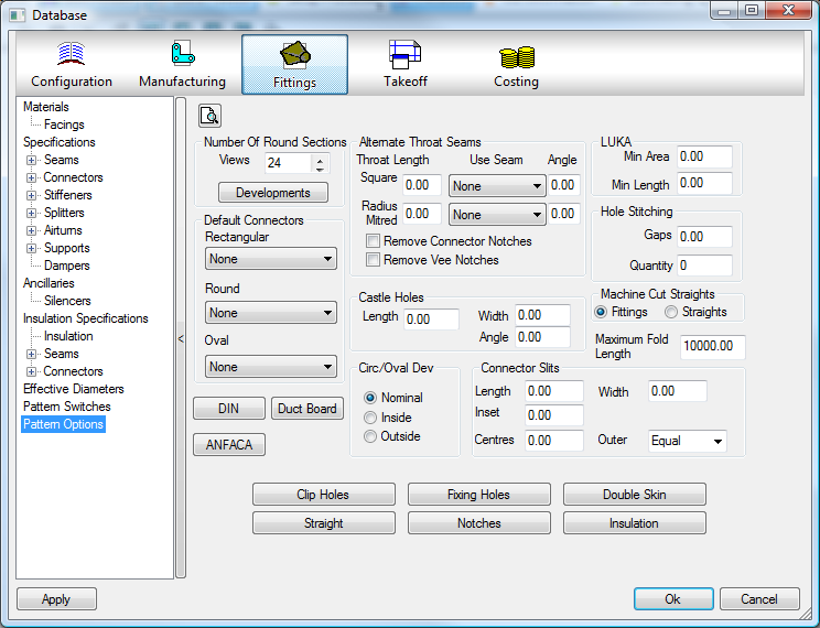
There are a variety of different options within the pattern options settings that influence how Notches, Connectors and Seams are defined within the program.
To access the Pattern Options click File  Setup Database Fittings Pattern Options or select the Database icon from the Utility Bar.
Number of Circular Sections
This options sets the number of lines that the circular profiling sections are made up from. The higher this number, the more accurate circular profiles will be.
- The Views setting controls the number of faces used to model circular & oval ducts in 'Takeoff' views.
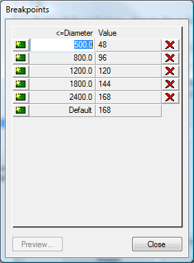
- Click on Developments to control the number of lines the circular profiling sections are made up from. In general the higher this number, the more accurately circular profiles will be cut.
- The <=Diameter column defines the breakpoints at which the number of development lines will increase.
- The Value column on the right is the number of circular sections for the given diameter and can be altered by clicking in the box and adjusting the value in increments of 24 via the Up/Down arrows.
- Use the Green 'New' icon to create an additional diameter breakpoint or the red cross 'Delete' symbol to remove a breakpoint. Default Connector.
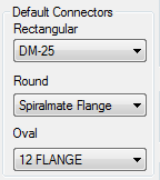
Default Connectors
Specifies the default Connector that will be used for Rectangular, Circular, and Oval duct. These are taken directly from the connectors that are set up in the database.
DIN
The DIN option is specific to German users only. If more information is required, feel free to contact Autodesk: Tel: + 44 1253 792112 Fax:+ 44 1253 792169
ANFACA
The ANFACA option is specific to Spanish users only. If more information is required, feel free to contact Autodesk: Tel: + 44 1253 792112 Fax:+ 44 1253 792169
Duct Board
Duct Board is a phenolic foam duct system that uses specific patterns created by Autodesk for cutting on a router based cutting table. Clicking on this button will open a window for editing Duct Board specific options. Details on setting up a Duct Board machine can be found at Ductboard. If more information is required please contact Autodesk: Tel: + 44 1253 792112 Fax:+ 44 1253 792169
Alternate Throat Seams
On some rectangular fittings it is necessary to use a different seam for the throat than that used on the rest of the duct. The normal seam can be entered during pattern takeoff, but if the throat part of the fitting falls into the criteria set here, these settings will be used to generate its seam.
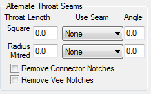
- If the throat length of a fitting is equal to or less than the value entered in the Throat Length field.
- The seam set up in the Use Seam field will be used.
- There are also options to Remove Connector Notches and Remove Vee Notches, tick as appropriate.
Castle Holes
This option allows the user to set the size and angle of tabs applied to Castellated Holes.
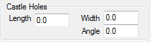
- In the Length field enter the relevant Length of the Castellated tab.
- The Width field sets the width of the tab
- The Angle field sets the angle at which the tabs will be cut.
Circ/Oval Dev
This option allows the user to define how circular and oval developments are calculated. The three diameter types of a circular pipe or fitting are Nominal, Inside and Outside. The terms apply to the position from which a diameter is measured.
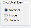
For further information refer to Circular Developments topic in the On-line help.
Connector Slits
Connector slits are set up here. These are slits that run parallel to a rectangular connector end, and are primarily used for attaching clip-on connectors such as TDC or CGF.
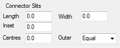
- The Length field sets the length of each slit.
- The Width field sets the width of the slit/slotted hole
- The Inset field sets the distance of the slit from the end of the duct before allowances are allowed. This must be less than the allowance for the connector or slits will not be added.
- The Centres field sets the distance between the centres of adjacent slits. If the duct end is smaller than this distance, slits will not be added.
- The Outer field determines the distance from the seam edge that the first holes will appear, if "ears" are applied then Negative values can be entered.
 f
f
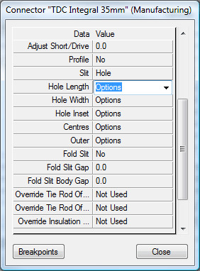
The Width and Outer Fields are for adding parameters for Holes on the Connector.
LUKA
The LUKA option is specific to Dutch users only. For more information see LUKA Patterns, or feel free to contact Autodesk: Tel: + 44 1253 792112 Fax:+ 44 1253 792169
Hole Stitching
This option sets the default number of stitches and the gap size for cutting inner island holes in a part.

- The Gaps field sets the distance between stitches to apply to the cutting of a hole.
- The Quantity field sets the default number of stitches to apply to the cutting of a hole.
Clip Holes
Clip holes are used for Valve boxes and lagging. The option needs to be enabled for individual patterns.
- Click the Clip Holes button and the Clip Holes dialogue box will appear.
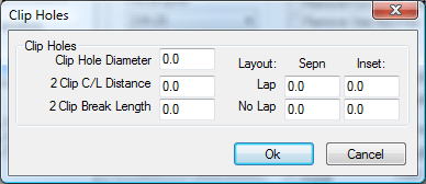
- The Clip Hole Diameter sets the hole diameter.
- The 2 Clip C/L Distance sets the value of the Centre Line offset if using 2 rows of holes.
- The 2 Clip Break Length: If the length exceeds this value the number of clips is doubled.
- The Lap / No Lap field sets the Lap size with allowance or without allowance.
- The Sepn field sets the distance between the 2 holes.
- Inset sets the inset distance from the end of the part.
Straights
The Straight option works solely when using Pattern Number 866. This pattern allows the user to produce straight, using either a decoiler or a plasma cutter. The criteria for defining which process will be used is briefly explained below.
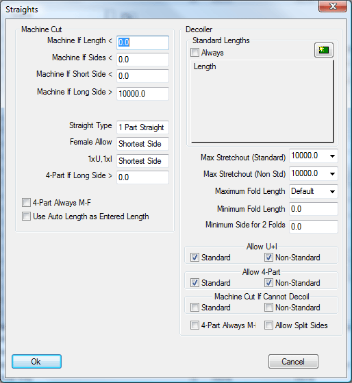
The Machine Cut section allows the user to set a criteria which will determine when the Straight will be machine cut and how it will be formed.
- The Machine If Length< field allows the user to enter a value. If the length of duct is shorter than this value it will be machine cut.
- If all four sides of the duct are below the value set in the Machine If Sides< field, the straight will be machine cut.
- If the shortest sides of the duct or less than the value entered in the Machine if Short Side< field, the straight will be machine cut.
- If the Longest side of the duct is greater than the value entered in the Machine If Longest Side> field, the straight will be machine cut.
If any of the above criteria is met, the straight will be machine cut, otherwise the program will use the Decoiler options to see if the straight can be decoiled.
The following options will determine how the straight will be formed, if it is machine cut.
- Straight Type: This option sets the default type of straight to be plasma cut. If the straight is too large to fit on the sheet, the other types will be tried in the following sequence, beginning with the default type: 1 Part Straight; 1xU, 1xI; 2xL; 4xI,M-M,F-F; 4xI,M-F
- Female Allowance: Determines the side of the fitting to which the female seam allowance is applied when there is a choice. 1xU 1xI: Determines which side forms the single panel when the straight is cut as a 1xU, 1xI type
- 4 Part If Long Side >: If the longest side of the straight is above this value then it will always be cut in 4 parts.
- 4 Part Always M-F: If enabled then the program will always put a male and female seam allowance on each panel when the straight is cut in 4 parts. If disabled, each panel would normally have 2 male or 2 female allowances unless this made the panel too large to fit on the sheet.
The Decoiler section allows the user to set how straight will be formed via the Decoiler.
Standard Lengths
The Standard Lengths section contains a list of lengths that are determined to be standard, i.e. you may have coils that are different widths but each coil would produce a straight standard to it.
- To add another entry click the new icon
 To remove an entry set its value to Zero. Note: The standard lengths table is not a collection of breakpoints, each entry must be matched exactly by the entered duct length. In most cases it is recommended that standard straight lengths be set up in the Specifications table in the pattern database rather than being entered in this table. If the length of the straight does not fall into the standard lengths list, the straight will be processed as if it were the normal coil straight fitting, Pat 35. In this case standard straight lengths are defined in the Specifications table in the pattern database.
 - If the Always tickbox is enabled, all straights entered using pattern 866 are treated as standard straights. If disabled, only straights of standard length are treated as standard; all others are treated as non-standard.
- Max Stretchout (Standard) & Max Stretchout (Non Std) Determines the maximum length of any single decoiled part for standard and non-standard straight lengths. An example of this would be if you were decoiling the sheet to fold in a press break and not on the coilline. The length of the sheet could be too long, making it difficult to handle. Once the length goes over this size, the straight type will be set to be made in 1xU, 1xI , then 2xL , until it fits. Note: Entering large values will ensure that straights are made in 1 piece, subject to the other options.
- Maximum Fold Length: Determines the largest fold allowed.
- Minimum Fold Length: Determines the smallest fold allowed. Both the maximum and minimum fold lengths are used to determine the final straight type. A 1 piece or 1xU, 1xI straight must satisfy both the maximum fold length and the minimum fold length check. If it fails, the type will be set to 2xL. This type will be used if it satisfies either of the minimum or maximum checks. Failing this check will set the straight to be made in 4xI sections.
- Minimum Side For 2 Folds: Determines the smallest side allowed when a part has more than 1 fold. If the smallest side falls below this value, the straight will never be made as a 1 Part or 1xU, 1xI type.
- Allow U+I: If disabled the straight will never be made as a 1xU, 1xI type.
- Allow 4-Part: If disabled the straight will never be made in 4 parts.
- Machine Cut If Cannot Decoil: This option is only used when the previous options for the decoiler do not produce any valid straight types. The most common reason for this is that the checks have determined that only a 4-part straight is valid but the 'Allow 4-Part' option is disabled. If this switch is enabled, the program will set the straight to be plasma cut, using the Machine Cut options, but ignoring the checks to decide if it should be machine cut. If this switch is disabled, the program will report the straight as being invalid.
- 4 Part Always M-F: If enabled then the program will always put a male and female seam allowance on each panel when the straight is cut in 4 parts. If disabled, each panel would normally have 2 male or 2 female allowances unless this made the panel too large.
- Allow Split Sides: This feature has been implemented for certain decoilers and should not be activated for general use.
Fixing Holes are mainly used with Insulation Patterns, and these holes can be applied to the seam of a pattern. The settings here determine how these holes are applied.
- Click on the Fixing Holes button.
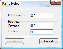
- The Hole Diameter field sets the diameter of the hole to be cut.
- The Hole Inset can be determined in two ways. The first is by setting a specific distance. In the Distance field, the value entered here will be the distance in, from either end of a section of a developed fitting. In the Fraction field, the value entered here will be the amount that any developed section of a fitting will be divided into to determine the inset position of the fixing holes. Note: If an amount has been entered into the Distance field, the Fraction field will be automatically over-ridden. Before the Fixing Holes can be used the Items tab within the patterns themselves has to be customized. To do this, follow these steps:
- Click Utilities > Item Folders.
- Click on the Round folder. Locate the Segment Elbow icon and right click on it.
- From the pop - up menu select Edit.
- The Editing Pattern Defaults view of the Segmented Elbow will now be visible.
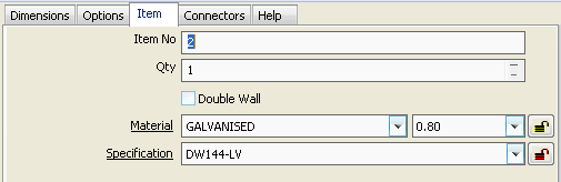
- Click on the Item tab. The Items will look similar to the one below.
- Along to top of the window clickTakeoff > Customize the following window will appear.
- Click on the Item Information tab.
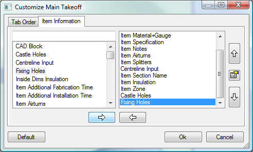
- The dialogue box that appears is split into two sections. The section on the left displays all the options that can appear in the Item tab and the section on the right shows the options that already appear in the Item tab.
- In the left hand section locate the option called Fixing Holes and click on it.
- Once it is highlighted, it needs to be moved to the right hand column. This is be done by clicking on the arrow pointing towards the right.
- The Fixing Holes option should now appear on the right, click OK.
- The Item tab should now have the Fixing Holes tick box displayed.
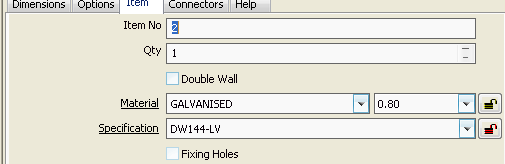
- Ticking this box will enable the Fixing Hole settings that have been mentioned earlier.
- This option will now appear in every fitting where Fixing Holes can be applied.
Notches
The Notches option allows the user to set up default notches that are used throughout CAM-Duct.
- Click on the Notches button and the following window will appear.
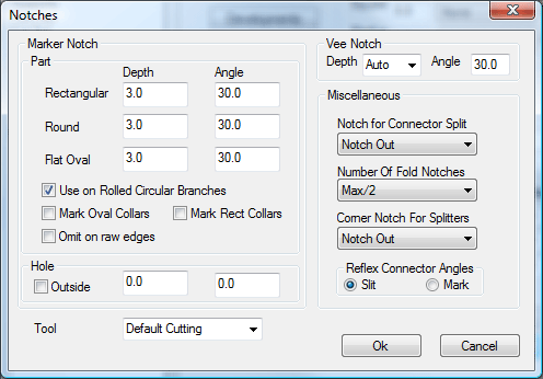
Marker Notch
The Marker Notch option allows the user to mark centrelines and fold lines on developments. The depth and angle of these points can be configured here by entering values into the relevant fields. Different Marker Notches can be set up different pattern types.
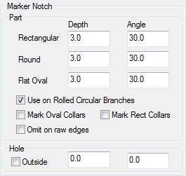
- In the Depth field enter the required depth of marker notch for Rectangular, Round and Flat Oval fittings.
- The Angle field sets the angle at which the notches will be cut.
- Enabling the Use on Rolled Circular Branches option will place a marker notch at the front and the back of the circular branch.
- These Settings can also be applied to Collars if the appropriate Rectangular or Oval Marking check box is selected.
- You can set this to not put a mark on an edge where no connector allowance has been applied by selecting the Omit on raw edges check box.
- The Hole options allow the user to notch ends of hole developments, when enabled on the pattern .
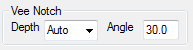
Vee Notch
This option allows the user to set a notch configuration for additional notches. This is set in the same way as the Marker Notches.
Notch for Connector Split
Specifies the default notch for connector split. The notch type is taken from the notches that are set up in the database.
Number Of Fold Notches
The number of fold notches denotes how many notches are to be cut out of a given size of duct to mark where it is to be folded.
Fold notches are used for marking out where the duct is folded from. The values are :
None = No Fold Notches
8,12,24 = Set values
Max = Maximum amount per part
Max/2 = Half of the maximum amount
Max/3 = One Third of the maximum amount
Max/6 = One Sixth of the maximum amount
Corner Notch for Splitters
If the software is used to generate splitters on some rectangular fittings, this option allows the user apply a notch to the corners.
- From the drop-down menu select a notch from the list available. These notches are pre-set in the Pattern Database.
Reflex Connector Angles
These allow connector ends to be marked with a slit or a marker notch if the angle between the sides exceeds 180 degrees.
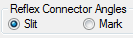
- The choices are Slit or Mark, check the desired option.
Double Skin
Although the Double Skin option is still available it has been superseded by the Double Wall option, which is available during Pattern Takeoff.
For a more information about Double Wall see the Double Wall section of the On-Line Help.
Insulation
This option allows the user to configure the way insulation is applied to patterns. This option is set up here, but each pattern needs to be individually customised to use this option.
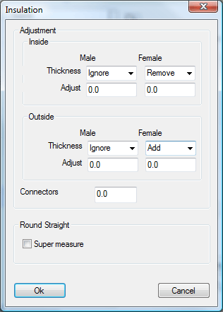
- If the Insulation type is selected as Inside, then the settings within the Inside section will be used.
- The Thickness field allows the user to choose whether an amount equal to the Insulation thickness is added or removed from Male and Female seams. There is also an Ignore option.
- Alternatively an amount entered in the Adjust field will add or remove a specified amount.
- The Outside section works in the same way as the Inside section.
- The Super measure tick box will add Pi x Insulation Thickness to each side of the insulation development to allow enough material at the outside edge of the Insulation. Will only work on outside insulation.