Square bends and tees often require air turning vanes to be fitted to assist the air flow. Different suppliers and types of airturns can be set up in the database. The main objective is to produce management reports that detail the airturn materials used and the airturn assembly cutting lists.
Please use the Navigation & Toolbars for information on how to access the Global database using your application.
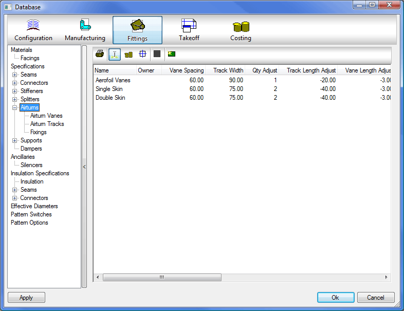
Double clicking on an entry, within the table, will bring up the following screen to allow you to edit the air turn details, clicking on the  Icon will create a new Airturn entry.
The options available in the database are as follows:
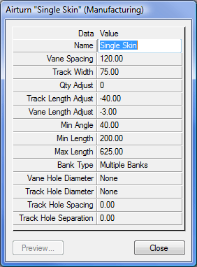
Name
The airturn is given a name for identification purposes.
Vane Spacing
The Vane Spacing dialogue allows the user to specify the distance, between the vanes, along the track.
Track Width
The Track Width dialogue allows the user to specify the width of the track onto which the Vanes are to be inserted. This is also used to aid in the calculation of the vanes by adjusting the calculated distance based on how far the track can be pushed into the back of the bend. If vanes need to be calculated from the throat of the bend, all the way to the back, set this value to zero.
Qty. Adjust
Can be used to add or subtract from the number of calculated vanes.
Track Length Adjust
The track length adjust value is subtracted from the calculated length of the track. This may also affect the number of calculated vanes.
Vane Length Adjust
The vane length is calculated from the duct depth, minus the value entered into the Vane Length Adjust.
Min. Angle
Airturns will not be applied if the fitting is entered with an angle less than this value.
Min. Length
Refers to the minimum length of track. If the calculated track length falls below this value then the Airturn will not be applied to the fitting.
Max. Length
Refers to the maximum length of track. If the calculated track length rises above this value then the Airturn will not be applied to the fitting.
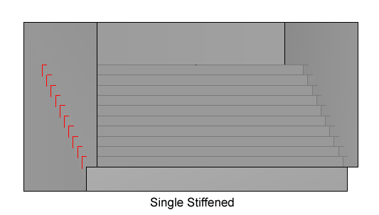
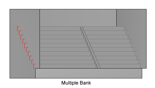
Bank Type
Can be set to either Multiple Banks or Single Stiffened. Multiple Banks will look at the Depth of the Duct and the Maximum Vane Length and calculate the number of sets of Airturns to fit.
|
|
Vane Hole Diameter
This option allows the user to specify whether the vane connecting holes should be pierced, marked, omitted or specified with a value.
Track Hole Diameter
This option to specify whether the track connecting holes should be pieced, marked, omitted or specified with a value. If the hole diameter is selected as Pierced or a Value then the Fitting cheek panels will be cut with the holes.
Track Hole Spacing
The value entered here will specify the distance between the track connector holes in the column for fixing to the duct.
Track Hole Separation
This option allows the user to specify the distance between the two sets of track connecting holes.
Printing Airturn Reports
A print report can summarise the Airturn material requirements and cutting list.
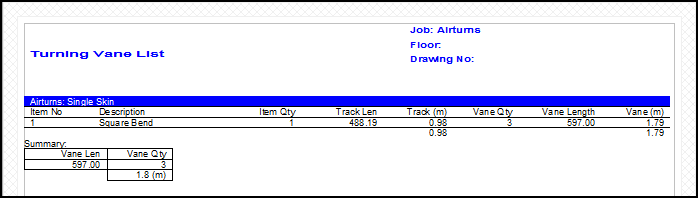
Track Lengths, Vane Length, and Vane Quantity are all calculated using the following:
Track
For the example above a 400 x 600 Square Bend would produce an unadjusted length of SQRT ( 400 ² mm + 400 ² mm ) = 565.69mm Because the Track Width = 75mm, it will not fit exactly in the corner, the corner adjust will be 37.5mm. The Track Length Adjust from the table = -40mm. So the adjusted Track Length will equal 565.69mm - 37.5mm - 40mm = 488.19mm.
Vane Length.
Duct Width = 600mm
Vane Length Adjust from the table = -3mm which allows for Track Thickness and Duct Gauge.
So the adjusted Vane Length equals 600mm - 3mm = 597mm.
Vane Quantity
Vane Spacing from the table = 120mm
The quantity is calculated using the adjusted Track Length divided by Vane Spacing which equals 488.19mm /120mm = 3mm (rounded down). Number of Vanes = 3
If needed the Qty Adjust can be used to make the quantity of vanes increase or decrease.