Most Ductwork manufacturers have to work to a Specification. These are a set of rules that govern how ductwork is made and installed. Setting up a Specification correctly in our software will allow the software to determine certain information automatically, instead of the user having to choose each of these factors individually.
Please use the Navigation & Toolbars for information on how to access the Global database using your application.
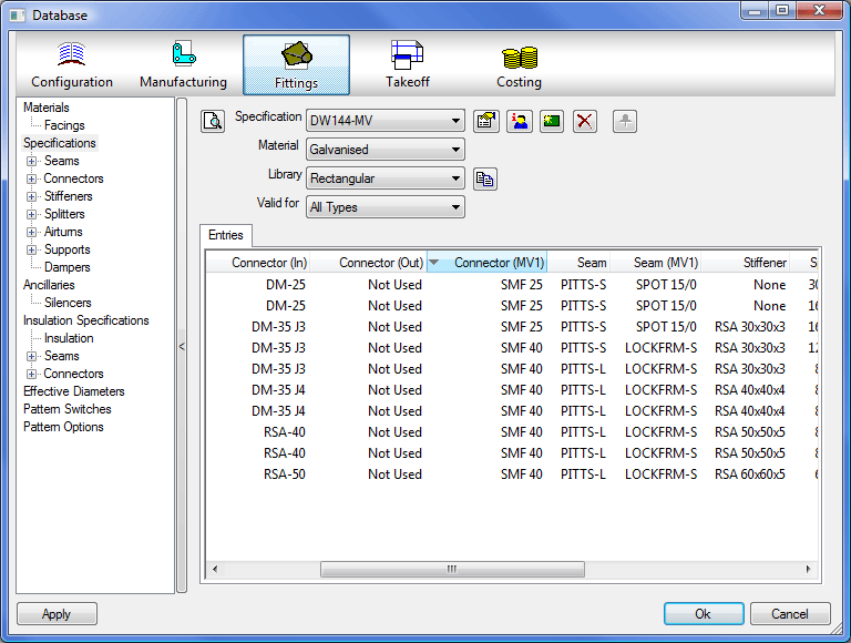
Setting up the Specifications enables the automatic selection of parameters. Some Patterns have the ability to override the Specification settings. It is not essential for Ductwork Users to set up or use Specifications, however, when the specification table is correctly set up, it makes the operation of adding items to a job considerably easier and quicker. It is necessary to set up Connector and Seam parameters before defining Specifications.
The Specification properties can be accessed by clicking on the Properties icon  .
.
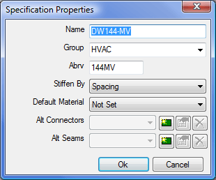
Name
The descriptive name given to identify the Specification.
Group
Specifications can be grouped together into separate Groups, to create a new Group type the name in this box. Specifications can then be moved to other Groups by selecting the group from the pull down box.
Abrv
An abbreviated name used in identifying the Specification and on Reports.
Stiffen By
This allows the specification to set the number of Stiffeners used on an Item to be determined by Spacing or by an Input Value.
Default Material
The material picked up by default when using this Specification in TakeOff.
Alt Connectors
The Alt Connector allows the user to allocate a different set of Connector Information to an Item File where you still want the Item to follow the rest of the Specification Parameters.
Alt Seams .
The Alt Seams allows the user to allocate a different set of Seam information to an Item where you still want the Item to follow the rest of the Specification Parameters
Selecting the New icon in Alt Connectors or Seams will let the user enter a name for the Alternative Field, this will then be displayed in the Specification Table as an Alternative Connector and/or Seam.
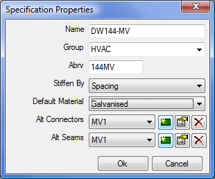
In the example above an Alt Connector and Seam were created called MV1, this then creates the extra Columns in the specification Break table.
The Item file has to be edited and the Alternative Connector and/or Seam name is entered into the Alt column.
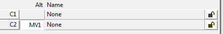
This will then apply the normal Specification entry to the Item as well as the Alternative Entry.
Modifying Specifications
- Double click an entry to edit the details.
- To create a new entry in the specification, Right-click on the table and clickNew.
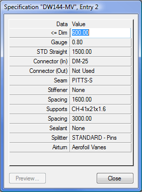
<= Dim
The figure input here will specify that a fitting with a Longest Side value of up to and including that figure will use the factors set here.
Gauge
This specifies what gauge the material will be.
STD Straight .
Specifies the standard straight length
Connector (In)
Specifies the type of connector used.
Connector (Out)
Specifies the type of connector used.
Seam
Specifies the type of seam applied to the fitting.
Stiffener
Specifies the type of stiffener applied to the fitting.
Spacing
Specifies the break points for the placing of the stiffeners.
Supports
Specifies the type of supports for this fitting.
Spacing
Specifies the break points for the placing of the supports.
Sealant (Rectangular Patterns Only)
Specifies the type of sealant applied.
Splitter (Rectangular Patterns Only)
Specifies the type of splitter applied to the item.
Airturn (Rectangular Patterns Only)
Specifies the type of airturn applied to the item.
Collar (Round, Flat Oval, and Standard Only)
Specifies the collar type applied to the item.
Damper (Round, Flat Oval, and Standard Only)
Specifies the damper type applied to the item.
Pipe OD
Used in CAD-Duct.
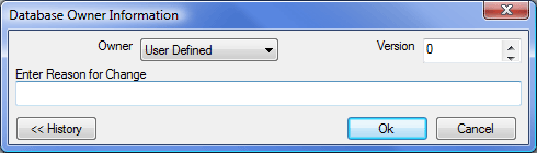
Owner Information
The Owner Information Icon  displays details on who created the specification and any revision changes that may have been made.
New Specification
- Click the New
 icon.
icon. - A dialogue box will appear asking if you want to create a copy of an Existing Specification, this can speed up the entry of information if the Breakpoints are similar to the currently open Specification.
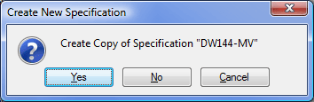
- If Yes is selected then the software will create a copy of the specification for the user to edit, if No is selected the Create New Specification dialogue will appear.
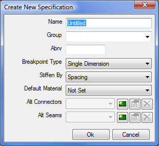
Name
Gives the Specification a descriptive name.
Group
This option enables you to create groups and add specifications to existing groups.
Abrv .
Here you can give the Specification an abbreviated title for use in Reports
Breakpoint Type
There are 4 options to specify the Breakpoint type.
- Single Dimension.
- LS / SS Dimensions.
- Single Dimension + Length.
- LS / SS Dimensions + Length.
The type of breakpoint used will determine what criteria the specification will look for before applying the breakpoints.
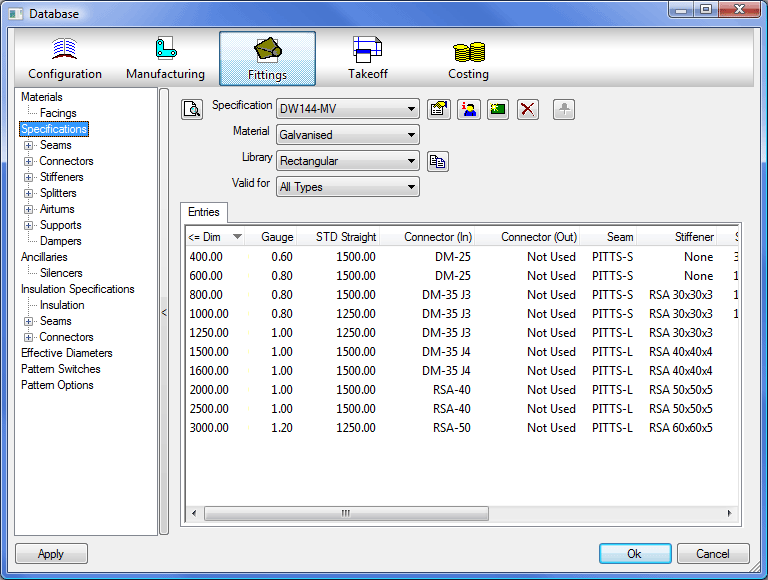
Single Dimension
This specification will look for the longest side of the duct to determine what values to apply to the pattern. The figures inputin the less than or equal to Dimension field will create the breakpoints.
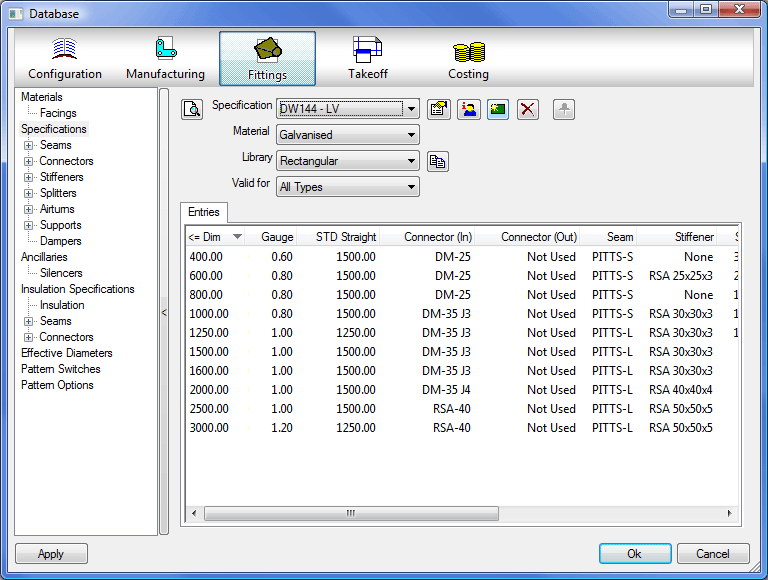
In the example above, a Single Dimension specification with an item of Duct where the longest side dimension that is less than or equal to( <= ) 400mm will apply 0.60 Gauge Galvanised, a DM-25 Connector, PITTS-S Seam, and No Stiffener to the duct. Whereas a duct with it's longest side less than or equal to 600mm but greater than 400mm will be applied 0.80 Gauge Galvanised, DM-25 Connectors and a PITTS-S Seam and a DM-25 Stiffener.
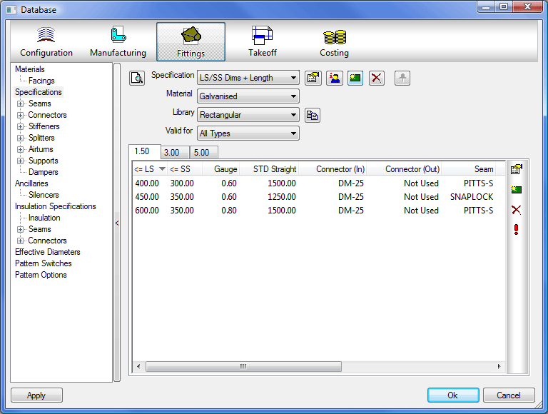
LS/SS Dimension
This specification looks to the longest side and the shortest side of the duct to determine what criteria are applied to the duct.
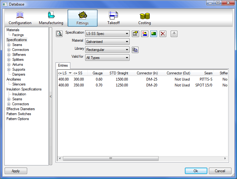
For example, in the table above, a duct with a long side of equal or less than 400mm and a short side of equal or less than 300mm would be applied 0.60 gauge Galvanised, DM-25 connectors, and a PITTS-S seam. Whereas a duct with a long side of 400mm and a short side of less than or equal to 350mm but greater than 300mm would be assigned 0.70 gauge Galvanised, DM-25 Connectors, and a SPOT 15/0 seam.
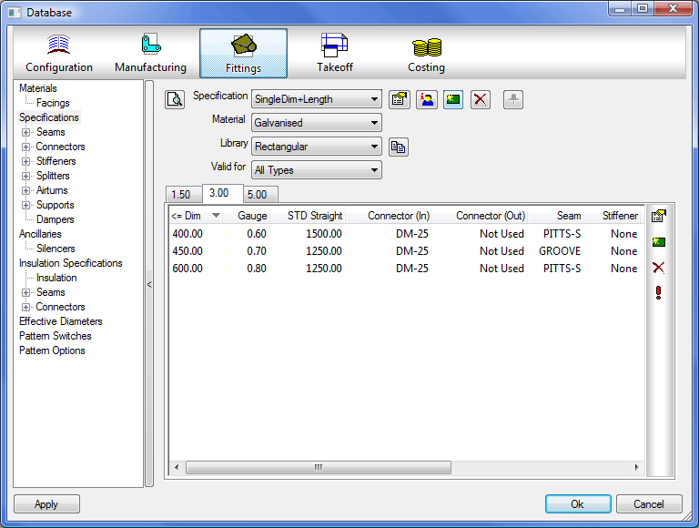
Single Dimension + Length
This specification is similar in some respects to the LS/SS specification but this time it looks for the longest dimension in the Width and Height field and looks at the length of the duct to create further breakpoints. The length breakpoints are input by creating new tables in Tabs.
- A new tab is created by clicking on the green New icon .
- An existing tab length can be edited by clicking on the Edit Length icon .

In the example above a duct with a long side of 450mm and a length of 1.5m or less is allocates 0.60 gauge galvanised, DM-25 connectors and a SNAPLOCK seam. Whereas in the table below the same duct but with a length of 3m will allocate it 0.70 gauge galvanised, DM-25 connectors, and a GROOVE seam.
LS / SS Dimensions + Length
This specification will look at all dimensions on the duct and apply the criteria accordingly, is setup the same way as LS Dimensions + Length but with the added Short Side dimension.