|
The Sizes command allows the duct size dimension to be displayed on the drawing.
- Select
 Edit Main Database.
 - Scroll down to the Size Text options.
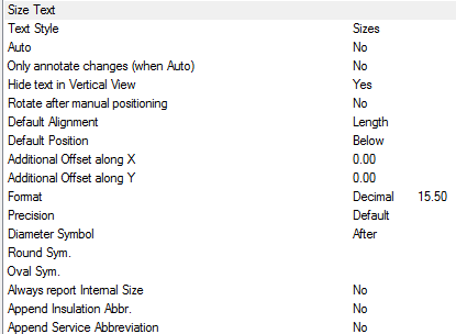
- The Style box is used to specify the AutoCAD Text Style to be used. If the Text Style Sizes is not present, then Standard is used by default.
Options
- Text style - Text properties taken from Style named here, if the style dose not exist "Standard" is used. Height, Width, Font etc are defaulted from style. > If only displaying in Paper, Height should be size required for plotting.
- Auto - Automatically applies the Size label to each item drawn.
- Only annotate changes (when Auto) - Only applies a Size label, when the items are different in Size or cross section from the previous item connected from Note : Option Auto must be set to Yes to utilise the Only annotate changes.
- Hide text in Vertical View - Hides stacked annotation in Vertical views, e.g. for a riser viewed in Plan would only display the base items' annotation.
- Rotate after manual positioning - An option to rotate the Size label; useful if the Label alignments option do not allow desired Alignment because of UCS or Item rotation.
- Default Alignment - Sets the annotations' alignment: View, Length or Connector (default Length).
- Default Position - Sets the annotations' alignment: Below, Middle or Above (default Below).
- Additional Offset(s) X, Y - Allows an additional offsets from the default Position.
Format
If the Format option is set to value greater the 1, then the above settings are over-ridden as follows:
- 1 - Scientific 1.55E+01
- 2 - Decimal 15.50
- 3 - Engineering 1'-3.50"
- 4 - Architectural 1'-3 1/2"
- 5 - Fractional 15 1/2"
Precision
If set to -1, precision is controlled by the AutoCAD - Format Units setting. If set to 0-7, precision is controlled by CADmep+ (zero to seven decimal places).
- 0
- 0.1
- 0.12
- 0.123
- 0.1234
- 0.12345
- 0.123456
- 0.1234567
- 0.12345678
Diameter Symbol
- Before - Displays the Diameter Symbol before the Size label
- After - Displays the Diameter Symbol after the Size label
- None - No Diameter Symbol is displayed
- Round Sym. - Enter the custom code for the desired Round symbol
- Oval Sym. - Enter the custom code for the desired Oval symbol
- Always report internal size : If to report "Airway" size or internal metal size excluding Matl thickness / gauge.
Append Service Abbreviation
- No
- Before - Service Abbreviation
- After - Service Abbreviation
- Append Insulation Abbr. - Insulation Abbreviation
- Imperial - If checked uses the AutoCAD - Units (see Format settings below)
- Imperial - If un-checked the Formatting is Decimal e.g. 15.25
Using the Sizes command
- Click the Sizes icon
 .
. - Select the Items to display the sizes. This can be done using any of AutoCAD normal selection commands.
- Right click to execute the command.
The Sizes should now be displayed. The Sizes text can be moved and rotated using the AutoCAD Grips or using the CADmep+ Move Text  and Rotate Text
  commands.
Additional Notes:
-
Selecting and reapplying any of the CADmep+ Label commands will toggle the Label On or Off.
-
If the Label is toggled Off then On again it will remember its original position and rotation.
-
If no Annotation is displayed check that the AutoCAD Text Style has been setup correctly.