Splitter Vanes are required by some Ductwork Specifications to assist the air-flow around bends. Splitters can be applied to several of the Radius Elbow and Breeches patterns.
Please use the Navigation & Toolbars for information on how to access the Global database using your application.
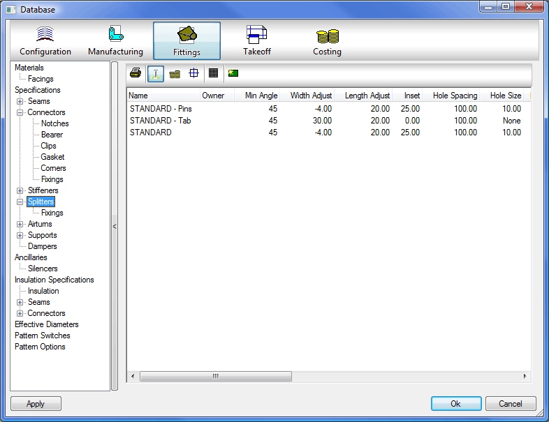
Manufacturing Settings
- Click the Manufacturing button.
- Double-click an entry to change the values.
- Right-click and choose New to create a new entry or click on the
 icon.
icon. 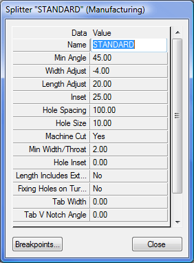
Name
Enter a description to help identify the Splitter.
Min Angle
Enter the Minimum Bend Angle greater than and including the value at which Splitters are required. Typically this will be 45, 75 or 89 degrees.
Width Adjust
Length Adjust
The calculated Vane Length can be adjusted for an allowance that can be rolled over to form a safety edge. This value is added to or subtracted from the Vane Length.
Inset
Determines the Inset from the Radius point at which the Vane will start.
Hole Spacing
If Splitter Vane fixing Holes are to be Marked or Cut, enter the value for the Hole spacing.
Hole Size
The options are:
- Pierce: The Plasma Torch will pierce at the Hole centre.
- Mark: The Marker Tool will Mark the centre of the Hole.
- Value: Enter the Diameter of the Hole to be cut.
Machine Cut
Toggle Yes or No.
Min Width / Throat
Sets a minimum size the width / throat must be before splitters are required.
Hole Inset
Determines the distance from the edge of the splitter that the first and last hole will be.
Length includes Extensions
Toggle Yes or No.
Fixing Holes in Turnover
This field determines whether or not fixing holes will be placed in the turnover or not.
Tab Width
This field determines the width of the tabs on the turnover, choose either Yes or No.
Tab Vee Notch Angle
This field allows the user to set the angle of the vee notch that will be placed in the turnover.
Tab Length
This determines the length of the tab along the Splitter.
Tab Quantity
This allows the user to determine the Quantity of Tabs on the Splitter, if left at 0 it will add tabs along the Full Length of the Splitter. A Value will place the tabs equally along the Splitter.
The splitter now needs breakpoints applying to it. This allows different amounts of splitters to be produced for different widths of duct.
Breakpoints Click on the Breakpoints button to access the Breakpoints dialogue.
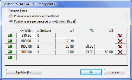
Position Units
Two methods for calculating splitter spacing are available when you click the Breakpoints tab. Choose the method required.
Positions are a distance from the throat
When this option is used the Vane positions entered for fields #1, #2, and #3 are absolute distances from the centre of Bend Radii. The <=Width (less than or equal to) field will determine when the breakpoint will be applied. In the example above, a duct width a width of less than 399.9mm, will not have splitters applied. A duct with a width of less than 800 but greater than 399.9 would get 1 splitter.
Positions are a percentage of the Duct Width from the throat
When this option is used the Vane positions entered for fields #1, #2, and #3 are percentages of the Duct Width taken from the centre of the Bend Radii. The <=Width (less than or equal to) field will determine when the breakpoint will be applied as explained above. In this case however, the figures in put in the 3 fields would normally be around 50% for 1 splitter, 33.3% and 66.6% for 2 splitters and 25%, 50% and 75% for 3 splitters.
Estimating Settings
- Click the Estimating button.
- Double-click an entry to change the values.
- Right-click and choose New to create a new entry or click on the icon.
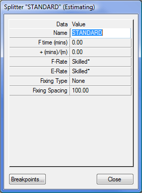
Name
Enter a description to identify the Splitter.
F-time (mins)
Sets the time required to manufacture the splitter.
+(mins)/m
A tolerance setting which allows the fabrication time to increase dependent in any increase in length.
F-Rate
Sets the Fabrication rate for this splitter. The available settings are Unskilled, Low Skilled, Skilled, and High Skilled. The values for these rates are set in the Costing Database, in Sections and Rates.
Fixing Type
From the drop-down menu you can view the fixing types entered in the Ancillary settings.
Fixing Spacing
This represents the distance between the splitters and is used in calculating the number of splitters required.
Breakpoints
Click on the Breakpoints button to access the Breakpoints dialogue.
See information on Breakpoints above.