Background: CAD Project Management
The project, usually a new building, may be broken down and modelled using AutoCAD Drawings as the main vehicle for creating and maintaining the Model. Each Drawing will represent an area of the Building, which includes Ground Work, Building Work, and some Services. The Drafting may be undertaken by a centralised design team or may be distributed between different Contractors or by using sub-contract draftsmen. The Drawings may be shared on an Intranet, and are possibly collected and passed through a Modelling Package to check for co-ordination It is the task of the CAD Project/Drawing Office Manager to establish the standard operating procedures that govern how Drawings are gathered, checked and distributed.
The CAD Project may use several specialised Bolt on Application Packages to draw the Objects that represent the Steel Work, Ductwork, Cable Trays, etc. Fast Track Buildings demand that the drawings continuously evolve and change.
A combination of Building Services Application Packages, the AutoCAD "XREF" facility, and down-stream Modelling Packages make all this possible provided procedures are established and followed.
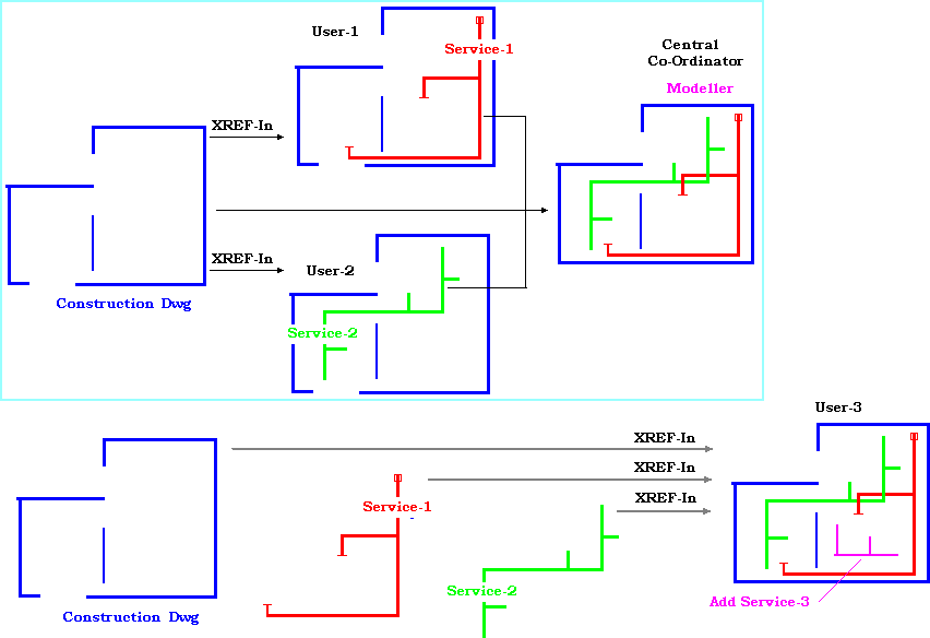
The Diagram illustrates how the Single Model is built up, verified and maintained. Different Applications could be used to draw each Service. The Application may be able to output Manufacturing and or detailed Management reports only at the application level. Using the XREF facility ensures User-3 cannot make changes to Services 1 & 2 Objects even if User-3 has access to the Objects used by User-1 or User-2. Completed, or in Progress Drawings may need to be distributed to other Users for a variety of reasons. From a Single Package, CAD-Duct is capable of Drawing many of the Services and outputting Manufacturing and Management data.
Guide lines to distributing Drawings that contain CADmep+ Objects.
The recipient only needs to View the Drawing and does not have CADmep+, therefore:
- Should not make any changes.
- Have requirements to interrogate certain Object Properties through a COM Interface.
- Does not need to use the CADmep+ Management Information System for detailed BOM Reports.
Open the Drawing using the latest CADmep+ Object Enabler.
The Drawing will be displayed, as drawn, using the Drawing's own embedded Database. From the COM interface the following data should be available: (AutoCAD Properties) Item No, Service Name, Section Name, Elevation, Product Name, End Sizes+ Connections, Area, Weight, and Custom Data Fields. The above data is also available within 3rd party applications that make use of the Object Enabler i.e. Navis.
The recipient is not permitted to make changes but needs to extract Management Information, for example detailed BOM's at the CADmep+ Application level:
- Requires CADmep installed as an Application in ADT or AutoCAD.
- Load the CADmep Application and Open a single Drawing using XREF.
- Design or import the required Report Templates.
We strongly recommend that only a single Drawing be opened as an XREF for Management reporting.
Alternatively the Drawing could be opened with the option to 'use it's own embedded Database' rather than the Database that exists on the users system. This is basically the same as using XREF, but does allow editing using the original database. There is the danger that the user could make changes to the original drawing and invalidate the design. It is recommended that the original author of the drawing make any changes required. To open a Drawing with its embedded database, refer to the Database Selection topic.
The recipient is required to modify data for preparing Pre-Fab Drawings.
- The modified original drawing will not be re-imported into the Model
- Requires CADmep installed as an Application in ADT or AutoCAD.
- Load the CADmep Application and Open the single target drawing. Other drawings may be required through XREF.
- Select each Pre-Fab section and save with the Spool Command
The recipient is required to open one or more drawings, some of which contain CADmep+ Objects for reference. Then add a New Service using CADmep+ Objects.
- Requires CADmep+ installed as an Application in ADT or AutoCAD.
- Load the CADmep+ Application, Open a New Drawing and XREF in the required drawings.
- Add the New Service using the CADmep+ Products that are available for drawing that Service.
The recipient is required to open one or more drawings, some of which contain CADmep+ Objects. Then be free to move, modify and add to existing services.
- Requires CADmep+ installed as an Application in ADT or AutoCAD.
- This scenario requires careful preparation.
- CADmep+ users could be using different Database's, Service and Product data.
The recommendation would be to:
- Open one of the Drawings that contain CADmep+ Objects using the Embedded Database option.
- Then XREF in any other required Drawings.
Make changes as required bearing in mind that new Objects will be added from your own Service set up. You should consider importing the Systems and Services used by the drawing originator.
The recipient is required to manufacture the Ductwork from the approved Drawing.
- Distributing Drawings to Ductwork Contractors for Manufacturing
The CAD Modelling Team will be using a Database which includes their interpretation of DW144, SMACNA Specifications to draw the Ductwork. On completion they wish to pass the drawing on to a selected Ductwork Contractor for Automatic Manufacturing. Partnership agreements between Building Services and Ductwork Contractors are the most efficient way forward. The CAD Team can then draw the Duct using the Manufacturers Database.
Why is this necessary to have this co-operation? A few pointers are listed below:
What to look out for:
This can be broken down into a number of areas:
- Rectangular Straight Ducts
- Manufactured Rectangular Fittings.
- Round Catalogue items
- Bought in Equipment.
Rectangular Straight Ducts
Ductwork Drawings typically contain 50%+ of Straight Ducts, where ever possible the Straight Ducts are manufactured to Standard Lengths. Using a Coil Line, it typically takes 2-5 minutes to produce a Straight Duct. To manufacture none standard Duct lengths could take 30 mins.
Straight Duct production is very much manufacturer specific. This is very much manufacturer specific with regard to Standard Straight Lengths and Connector/Seam type. For Example Shop-A might manufacture all the straights on a Plasma Machine, therefore they can work with Lengths up to 2980mm, stiffening required where applicable.
Manufacturer Shop-B could make the straights on a Decoiler machine, which restricts the length to the width of the Coils, usually 1250 or 1500mm. Connector own-metal allowances may also reduce the final Straight lengths available to be drawn in CAD. (TDC, TDF, S&D).
Shop A produces standard straights at 3000mm long (including connectors) up to a certain size, then 1500mm. Shop B produces straight 1510mm long, always uses MEZ Connectors. Shop C produces straight at 1475 when using S&D, then 1430mm when using TDC.
You can see if the CAD is drawn to Shop-A, then passes to Shop-C, all the straights need updating on the model. This can affect co-ordination, as connector positions would move, position of branches may vary, etc. There is a simple procedure in CadDuct to achieve this, Remove the straights and stretch a new one between fittings, this will replace with the correct lengths.
Manufactured Rectangular Fittings.
As a fitting is drawn, information about the Connector and Seam are saved with the model, CHSPEC will update this info to a different Manufactures Spec. Complications arise between duct shops as to 'Standards' for example Radius Throat values, Extensions for fitting connectors, stiffeners etc. Shop A might prefer 150mm throats; Shop B might use 1/2 width for throat (does not require splitters). Both are valid and correct, just preferences. Shop A may use Ductmate connectors (require at least 25mm straight on the fitting to attach it). Shop B may also use Ductmate but they always have 50mm of straight on the fitting extensions, so the manufactured part (and the model) is slightly bigger. The Fittings are usually manufactured on a Plasma Profiling machine. The Flat sheet fitting developments produced by the machine include, manufacturer specific, notching data that is essential to optimise production.
Round Catalogue
CADmep includes a Round Duct Library which is based on the data sheets supplied by a major supplier. Most round suppliers would stock the same diameters and overall fitting lengths should be the same, if there is a huge difference, then the round would need swapping out in the model, or buy from what it was drawn with. If the Ductwork Contractor were going to manufacture Round Fittings rather than Buy-In, then it would be prudent to discuss sharing the same Database.
Equipment
Should be OK, most suppliers would be spatially the same. (Fire Dampers, VCD's etc.) However connections may change.
CHSPEC Command
Built into CADmep+ is a utility to change the specification of the Ductwork. The Manufacturer can execute this Utility; select the objects to change and apply their own manufacturing specs to the selected Items. This takes care of differences in Connector, Seam and material thickness issues. It doesn't take care of the default Straight lengths used in the design. This will work for items that need to be manufactured on the Plasma machine, It will not 'swap out' what we call Bought In items, i.e. Fire Dampers, and generally round ducts. Round ducts are usually bought from specialist Round Duct Suppliers.
Conclusion:
So what does it all mean, well the model drawn by the CAD team will be spatially correct, co-ordination can be accomplished at the design stage. Can it be passed to a Ductwork Contractor and be auto-manufactured?
In theory, yes, provided some preliminary liaison between the respective CAD and CAM departments had been carried out before the CAD team started. In many cases the Ductwork Contractor will need to re-work the Drawing to a lesser or greater degree to enable manufacturing.
What can Autodesk do to help?
Autodesk should be consulted with regard to Auto-CAD-CAM before a new Project is started Autodesk are currently working on additional routines that will 'Check' the drawing for manufactures preferences, also provide routines to automatically amend Fitting extensions and update straight lengths.
Rectangular Duct simplification Rules, UK, for sub-sequent auto-manufacturing
- Standard Straights are 1500mm long and use a slip-on connector, Mez, D'Mate ....
- All Fittings have 50mm extensions and are not auto-extended in CAD.
- Bend Throat Radii are standardised.
What do you need from a specific Manufacturer before starting a project?
- The Manufacturer must be using CADmep and CAM-Duct.
- Export the System(s) used to manufacture Rectangular Duct.
- Export the DW144 Specifications to be used for the project.
- Information on how Straight Ducts will be manufactured
Example : Rectangular Duct
The CAD User would draw the illustrated duct to the DW144 Settings. This determines the Connector type and Standard Straight lengths. The CAD User also has an option to stretch the extensions on Fittings. This can reduce the number of Duct Items and minimise the need to manufacture small fill in straights.
Whilst it is not necessarily the job of the CAD User to optimise Production Costs, it helps if there is a close liaison between the CAD and CAM departments.
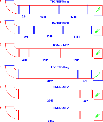
(1) & (2) both use Standard Straights made from a 1500mm Coil. The connector used, TDC/TDF, requires metal to be turned up to produce the Flange. The effective straight length is reduced to 1388mm.
(1) the Square Bend has been auto-stretched to limits defined in the CAD Users Database. If the limits had been longer, the need for the 524mm straight could be eliminated.
(3) Slip on Flanges similar to D'Mate or Mez have been used, these allow the full width of the Coil to be used as the Standard Straight length. 1505 = Width + 5mm gasket.
A few Ductwork contractors manufacture their straights from Sheets (3000 x 1500) which are then plasma cut. The finished lengths then depend on the connector type and the margin used around the plasma cut rectangles.
(4)-(6) represent different scenarios that this manufacturer might prefer.