There are several methods and approximations used for determining the pressure drops along runs of Pipe from the Source to the Outlets. It is important to know the PD losses in order to determine Fan and Pump sizes.
A common method is to determine the losses through the equivalent length of straight pipe and then add the pressure drops introduced by the turbulence caused by Elbows, Tee's, Reducers and Equipment.
The main variables of Flow, Velocity, Size and PD are linked.
Ducting:
Historically, the program has been linked to ASHRAE Tables that determine the additional Resistance (K value) to Flow, introduced by standard Rectangular and Round Fittings.
Many of the existing Duct Fittings are linked to the appropriate Tables through hard coded conditions.
For example a Rectangular Radius Elbow is dynamically linked to Table CR3-3 if Splitters are used and CR3-1 if not used.
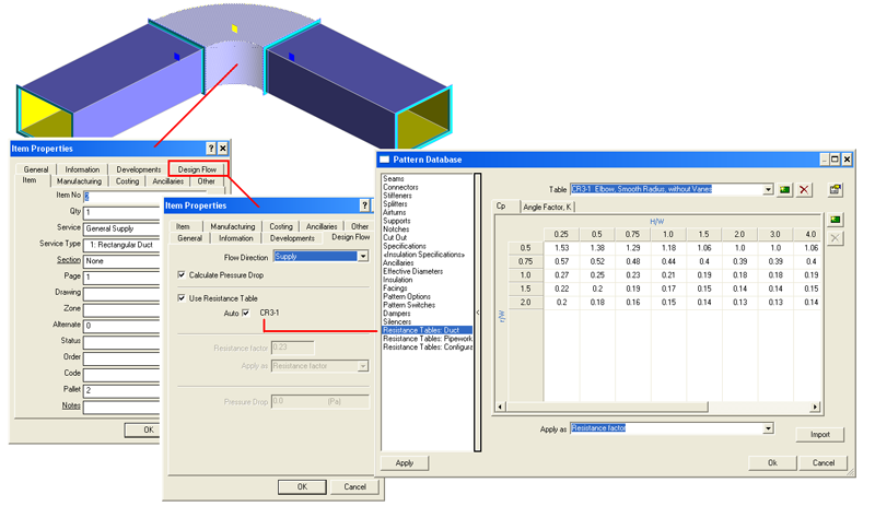
Some Fittings require more than one worksheet to calculate the Resistance. For example CR3.1 has a Sheet (Cp) that relates resistance to the Duct Width/Depth v Width/Throat Radius - the larger the Radius the less the resistance. A 2nd Sheet (Angle Factor, K) adds a correction introduced by the Elbow Angle: 30, 45 or 90 degrees.
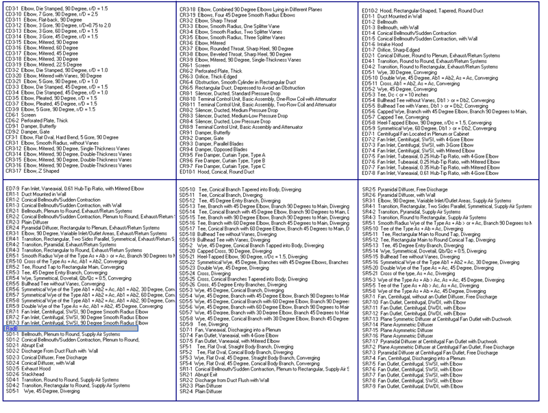
The ASHRAE Table names identify the type of Fitting to which the Tables are applicable:
"S" for Supply runs
"E" for Extract runs
"C" Common to both
"R" Rectangular Duct
"D" Diameter, Round Duct
RadB identifies a new table that was configured by the User.
Each Sheet relates specific fitting dimensions and in some cases flow rates, to resistance values.
Historically the software linked common Rectangular and Round fittings to the ASHRAE Tables. These are identified from the Fitting's Properties-Design Flow Tab. If Auto is ticked this enables the built in automatic conditions linked to the ASHRAE Tables.
This is not the case for more complex Fittings or for pipe work fittings.
The set up allows for Resistance Tables that can be assigned to a combination of Fittings or to treat the Fittings individually.
When using Design Line as the basis of pressure drop calculations, the Button Mapping can be configured to treat a NODE as a combination of Fittings and to assign the correct resistance Table.

|

|
Creating New Resistance Tables
The software caters for 2 types of Resistance Tables:
- Those that calculate the Pressure Drop using a Resistance factor.
- Those where the Pressure Drop is defined as an equivalent length of Straight Pipe.
The later is often most applicable to pipe-work. The ASHRAE Duct tables use resistance factors.
Example: Configuring a new Table to be used on a Grinnell Grooved Elbow using Equivalent Lengths:
From the Pattern Database choose Resistance Tables: Pipework.
Select New and enter the Table, Column, Row and Header names for the 1st Sheet.
Apply as: Equivalent Length .
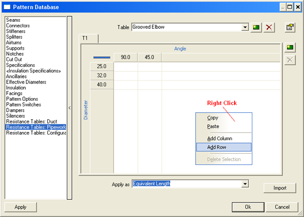
Right click in the Table to add Columns and Rows as required.
Select Columns and Rows with Arrow Tool to delete or add a column. Use Shift to select multiple rows/columns. (common functionality linked to most of MAP's Tables)
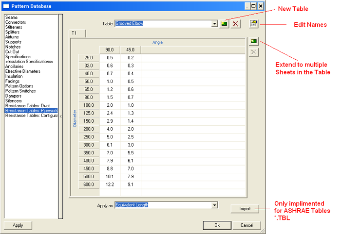
Add the required angles and equivalent Lengths.
For this example the data was taken from Grinnell's metric data sheets.
Multiple Sheets:
These are need for Branches and Tees where the flow divides and different parameters apply to the Main and Branch runs.
All the Resistance Table Data is stored in the Database Folder of the installation in 2 Files. Resistance.map Resistlink.map
Linking Resistance Tables to Fittings:
From the Pattern Database choose Resistance Tables: Configure
Select Pipework rather than Ductwork from the top centre drop down.
Start a New configuration and enter its description.
Choose the Resistance Table previously defined from the List: Grooved Elbow
The Header (Sheet) default to the 1st and only one in this Table.

Available & Links Columns:
The targeted Resistance Table needs to be linked to the Fitting Templates it refers to. Fittings are referenced by their CID No. Appendix A explains how to find a Fitting's CID No.
In many cases a single Fitting is linked to a Table, however the system caters for multiple Fittings.
Locate the CID No required from the Available List and move it across to the Links column. Add other CID No's if required.
Row & Column Calculations:
The Names assigned to the rows and columns in the Active Resistance Table will be displayed. In the example above these are Diameter & Angle. After the CID's have been assigned, the Dimensions associated with CID's are available to pick in the data entry boxes. Click in the box and pick the required dimension. The CID No. precedes each dimension. The entry can be made into a calculation by adding the +-*/ operators. Press the Space bar to toggle between the dimensions and the Operators. Brackets will sometimes be required to separate calculations. The exact syntax is important and a common error is in not having this correct.
If 2 CID's are active, the CID No differentiates the dimensions:
<4:Inner Radius> + <4:Top Width> /2 (<4:Inner Radius> + <4:Top Width>) /2
In the examples above, 4 is the CID No.
Assigning a Resistance Table Configuration to a single Fitting:
Right click on the Button associated with the required Fitting. Highlight the entry and click properties.
Select the Design Flow TAB.
Flow Direction: The Service should reflect if it is configured for Flow or Return. Some Fittings have different resistance characteristics when used for flow or return.
Calculate Pressure Drop should be ticked. Alternatively, un-tick and add a fixed known pressure drop.
Use resistance table should be ticked and a Table assigned. Alternatively, un-tick and add a fixed known Resistance value.
The Auto Box is only ticked for Duct Items that have pre-determined hard wired rules associated with the ASHRAE Tables.
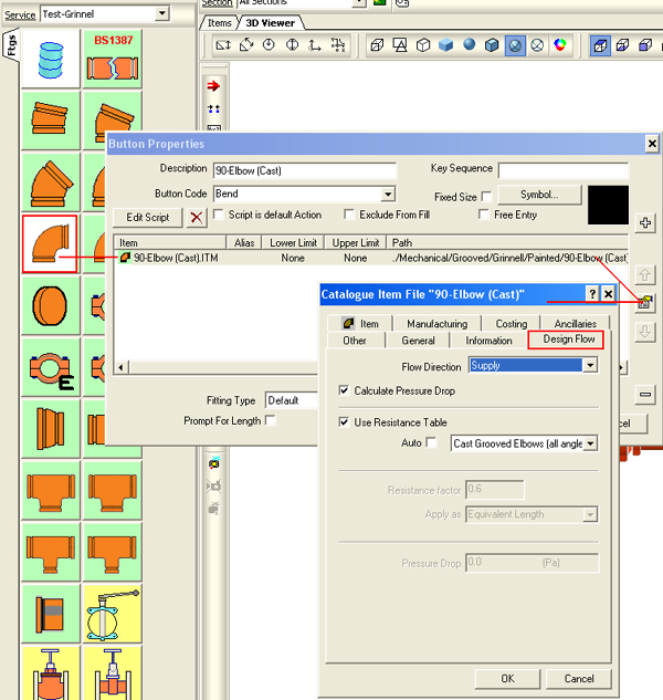
Note: This is the simple way to use Resistance Tables to calculate pressure drops.
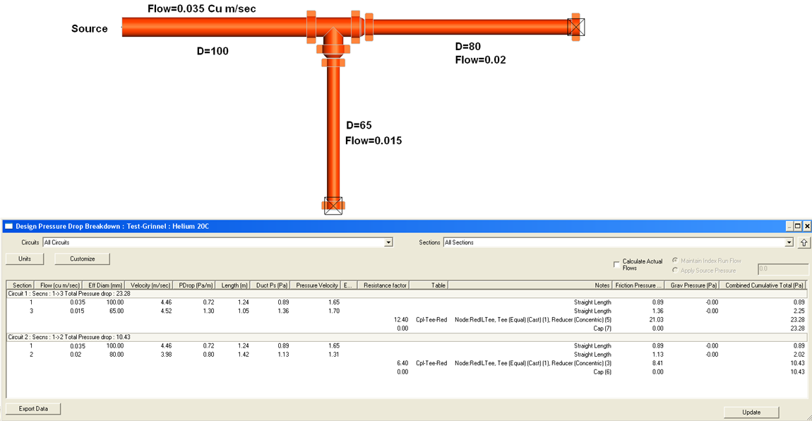
The Design Line Software is however more sophisticated and if a Filled Node contains more than one Fitting, the software examines the available Configurations (Rules) to find one that matches the fitting combination.
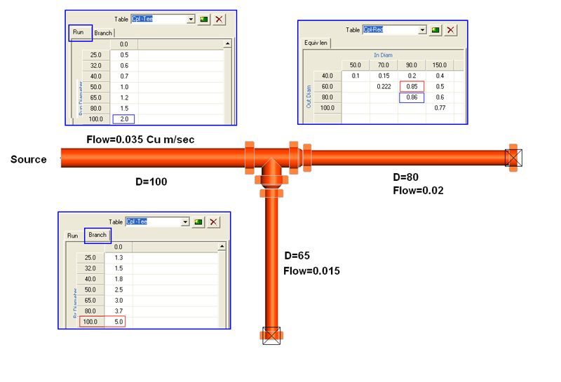
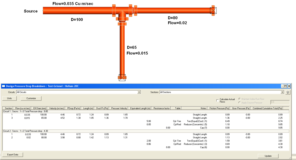
Example: Combo Tee and Reducers in each Leg:
Assume a Table is available that represents the resistance Factor when a Tee is close coupled with reducers at both ends.
The Rules (bottom right) link this Table (Cpl-Tee-Red) to the In and Out dimensions for the main and Branch runs of the combo.
If the design Line introduces a Node that includes the Fittings (CID=2044, 2051, 2051) it applies the rule.
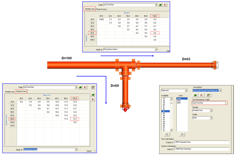
If it cannot find a Rule to match the combo, it drops through to individual Resistance/Equivalent Length Tables.
Appendix A
Determine the CID No of any Item in a Service:
It is necessary to know the Fitting CID No's that a particular Resistance Table will be linked to. For example the Grinnell grooved Elbow is based on CID =2523.
Right click on the Button and select Button properties. Highlight the required Item and click on the properties button. The CID No is displayed from the general Tab.
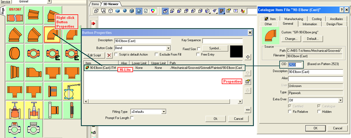
Later we link the Resistance Tables to the relevant products in the Services.