Header and Footer Layouts are used to displayed selected information at the top (header) and bottom (footer) of requested reports. These can be created within any of the Report Layout options, saved, and then applied to any of the other Report Layout options.
- Select File
 Print Layout Item Reports.
 - CADmep users type REPORTS at the command line, this can also be accessed via the Shift/Right Click menu CADmep Cam/Print Report Layout Item Reports.
- The command line prompts: Select objects
- Type ALL or use any of the normal AutoCAD selection methods and confirm.
- CADmep users type REPORTS at the command line, this can also be accessed via the Shift/Right Click menu CADmep
- Click on the Header Layout icon
 on the toolbar along the top of the report builder. Note: If the Nest Layout option is selected the Header Layout icon will not appear, in this case click on the Header Layout button.
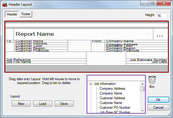
Designing the Header/Footer Layout
The Header/Footer buttons shows which part of the Header/Footer is selected for edit.
The Height field determines how many lines high the header/footer will be in use.
The Report design area ( highlighted in red above) allows the user to drag and drop objects wanting to be displayed into the available cells. Once applied into the cells, Right Click Properties to change any defaults for Font, size wanting to be used.
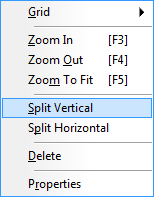
To create new cells on the design view, Right Click Split Vertical or Horizontal , creating a cell separator for use with the print objects.
Using available print objects from the purple area you are able to drag these over to the design area and place inside of the empty cell. Typing into the empty field at the top of the available list allows you to filter for certain print objects.
The New, Load and Save buttons allow the user to Save the layout, Load an existing layout or create a New layout. Once the design has been completed, this can be saved and used (loaded) on other reports. To remove print objects from the design view, drag and drop over the Recycle Bin. 
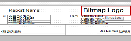
Applying a Company Logo
You are able to apply your own logo to the report or label.
Ensure the print object Bitmap Logo is placed onto the design view as shown below.
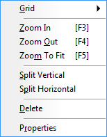
Right click on the Bitmap logo area select Properties.
You are able to Browse to your own logo which must be a PNG or BMP file format.
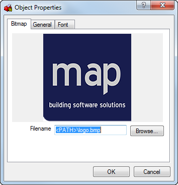
Click OK to accept any changes made or Cancel to exit without saving.