|
The Transition and Sets text option is used to display the Item Setting information. This Annotation is only applicable to certain Items - Taper for example.
The Transitions and Sets command uses AutoCAD Text Style to format its appearance.
- Select
 Edit Main Database.
 - Scroll down to the Offset Text options.
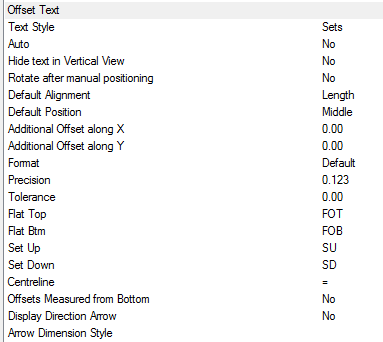
- The Style box is used to specify the AutoCAD Dimension Style to be used. If the Dimension Style Sets is not present, then Standard is used by default.
The following options are available:
- Text style - Text properties taken from Style named here, if the style dose not exist "Standard" is used. Height, Width, Font etc are defaulted from style. > If only displaying in Paper, Height should be size required for plotting.
- Auto - Automatically applies the Offset label to each transition item drawn.
- Hide text in Vertical View - Hides stacked annotation in Vertical views, e.g. for a riser viewed in Plan would only display the base items' annotation.
- Rotate after manual positioning - An option to rotate the Size label; useful if the Label alignments option do not allow desired Alignment because of UCS or Item rotation.
- Default Alignment - Sets the annotations' alignment: View, Length or Connector (default Length).
- Default Position - Sets the annotations' alignment: Below, Middle or Above (default Middle).
- Additional Offset(s) X, Y - Allows an additional offsets from the default Position.
Format
If the Format option is set to value greater the 1, then the above settings are over-ridden as follows:
- 1 - Scientific 1.55E+01
- 2 - Decimal 15.50
- 3 - Engineering 1'-3.50"
- 4 Architectural 1'-3 1/2"
- 5 - Fractional 15 1/2"
Precision
If set to -1, precision is controlled by the AutoCAD - Format Units setting. If set to 0-7, precision is controlled by CADmep+ (zero to seven decimal places).
- 0
- 0.1
- 0.12
- 0.123
- 0.1234
- 0.12345
- 0.123456
- 0.1234567
- 0.12345678
Tolerance - Enter the patterns offset value plus 0.1 e.g. patterns offset is 2, enter 2.1 into the Tolerance field to force reporting Flat Top/Flat Btm, overriding the label reporting the actual value - SU2 or SD2.

- Flat Top / Flat Btm / Set Up / Set Down / = - Controls the Annotation descriptions that are applied when using the Sets command.
- Centreline - Abbreviation displayed for the Centre Line value (Round only)
- Offsets Measured from Bottom - Checking this option forces all offsets to be measured for the Bottom (measured from Top by default)
- Display Directional Arrow - Check this option for a visual indication of the Set Up/Set Down direction
- Arrow Dimension Style - The box is used to specify the AutoCAD Dimension Style to be used. If a Dimension Style is not present, then Standard is used by default.
Using the Transitions and Sets command
Once the above steps have been completed the Transitions and Sets annotation can be applied to any appropriate Item's.
- Draw the Items as normal.
- Click the Transitions and Sets

icon. - Select the Items which Transitions and Set are to be displayed. This can be done using any of AutoCAD normal selection commands.
- Right Click .
The Item Transitions and Set text should now be displayed. The Numbers text can be moved and rotated using the AutoCAD Grips or using the CAD-Duct Solids/CAD-Mech Move Text  and Rotate Text
  commands.
Positioning Annotation as it is drawn
With the exception of CADmep+ Length Labels, all other Annotation can be positioned as it is drawn. The following instructions explain how to activate this feature.
- Select Edit Main Database.
- Select the CADmep+ Tab.
- Check the Prompt for Text Positions option at the bottom right of the menu.
- Click Ok.
Now each time a CADmep+ Label is selected and applied to an Item, the user will be prompted for the position. When multiple Items are selected for Labelling CADmep+ highlights the current Item in a selection with a dotted line type.
Additional Notes:
-
Selecting and reapplying any of the CADmep+ Label commands will toggle the Label on or off.
-
If the Label is toggled off then on again it will remember its original position and rotation.
-
If no Annotation is displayed check that the AutoCAD Text Style has been setup correctly.