Next, drill the single 4.5 mm hole.
- On the ribbon, click
CAM tab
 Drilling panel
Drill
Drilling panel
Drill
 .
.
 Tool tab
- On the Tool tab, click the
 button.
 - From the Sample Libraries > Tutorial tool library, select tool #33 - Ø4.5 mm drill.
- Click
 to close the Tool Library dialog.
 Geometry tab
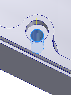
- Click the Geometry tab. Ensure that Selected faces is selected from the Hole mode: drop-down menu and that the Hole faces selection button is active.
- Select the lower cylindrical face of the last hole.
 Heights tab
Because this hole is counterbored, the cylinder starts a bit lower. Adjust for this by making the top start from the top of stock instead.
- Click the Heights tab.
- From the Top Height drop-down menu, select Stock top.
 Cycle tab
- Click the Cycle tab and select Chip breaking - partial retract from the Cycle type: drop-down menu.
Start the Calculation
- Click
 at the bottom of the Operation dialog box, or right-click in the graphics window and select OK from the marking menu, to automatically start calculating the toolpath.
The toolpath is calculated and shown in the graphics window.
Continue to To Machine the Counterbore...