The next step is to machine the two counterbores at the top left and right corners of the part.
- On the ribbon, click
CAM tab
 2D Milling panel
Bore
2D Milling panel
Bore
 .
.
 Tool tab
- On the Tool tab, click the
 button and select the tool #2 - Ø8 mm flat from the library.
 - Click
 to close the Tool Library dialog.
 Geometry tab
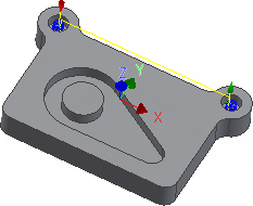
- Click the Geometry tab. The Circular face selections button should be active. Select the cylindrical faces of the two holes with the largest diameter at the top corners of the part.
- If necessary, zoom in and click anywhere on the cylindrical surface of the upper large hole.
- Do the same to select the other hole in the opposite corner.
 Passes tab
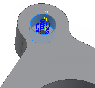
- Click the Passes tab. Here we control how the helix toolpath is calculated.
- Change Pitch to: 2.0 mm
Start the Calculation
- Click
 at the bottom of the Operation dialog box, or right-click in the graphics window and select OK from the marking menu, to automatically start calculating the toolpath.
The toolpath is now calculated and shown in the graphics window.
Continue to To Drill Holes...