There are four holes in the part; one is clear and three are threaded. Begin by drilling the three threaded holes with a 4.3 mm drill.
- On the ribbon, click
CAM tab
 Drilling panel
Drill
Drilling panel
Drill
 .
.
 Tool tab
- On the Tool tab, click the
 button.
 - From the Sample Libraries > Tutorial tool library, select tool #34 - Ø4.3 mm drill.
- Click
 to close the Tool Library dialog.
 Geometry tab
- Click the Geometry tab. Ensure that Selected faces is selected from the Hole mode: drop-down menu and that the Hole faces selection button is active.
- Select the cylindrical face of one of the three 4 mm holes.
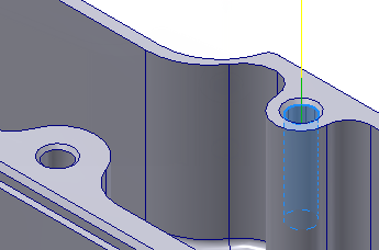
- Enable the Select same diameter check box.
Notice that the two other 4 mm holes are selected.
Depending on the selection, you may want to activate the Optimize order check box. The optimization reorders the holes to make the linking distance as short as possible.
Activating the Order by depth check box keeps holes with the same depth and plane together. Doing so may reduce the number of cycles in the output, but may not result in the shortest toolpath, even if Optimize order is enabled.
 Heights tab
For a drilling operation, the Heights tab controls the heights of each hole, and the heights used when moving between the holes. Because the holes are chamfered, the actual cylinders start a bit lower. This can be adjusted by making the top start from the top of stock instead.
- Click the Heights tab.
- From the Top Height drop-down menu, select Stock top.
 Cycle tab
- Click the Cycle tab.
- Select Chip breaking - partial retract from the Cycle type: drop-down menu.
- Change Pecking depth to: 2.5 mm
Start the Calculation
- Click
 at the bottom of the Operation dialog box, or right-click in the graphics window and select OK from the marking menu, to automatically start calculating the drilling toolpath.
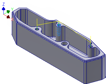
The calculated toolpath should look like this:
 Appearance panel
Wireframe
Appearance panel
Wireframe
 from the Visual Style drop-down.
 Continue to To Tap Holes...