A 2D Pocket strategy is now used to machine the internal pocket of the part.
- On the ribbon, click
CAM tab
 2D Milling panel
2D Pocket
2D Milling panel
2D Pocket
 .
.
 Tool tab
This operation uses a 10 mm bull nosed mill tool with a 1 mm corner radius to match the fillet radius at the bottom of the pocket.
- On the Tool tab, click the
 button.
 - From the Sample Libraries > Tutorial tool library, select tool #11 - Ø10 R1 mm bullnose.
- Click
 to close the Tool Library dialog.
 Geometry tab
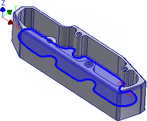
Now select the contour of pocket to be cleared.
- Click the Geometry tab. Make sure that the Pocket selections button is active.
- Select the face (or one of the edges) at the bottom of the pocket.
The selection should now look like this:
 Heights tab
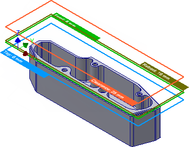
The parameters in this group control the different heights where toolpaths are generated. In this example, we want the 2D pocket operation to machine down to the bottom of the inside cut.
- Click the Heights tab.
- Set the Clearance height offset to: 15 mm
- Set the Retract height offset to: 10 mm
- Set the Feed height offset to: 8 mm
 Passes tab
This group controls how the 2D pocket toolpath is calculated. To clear out the pocket, a toolpath is generated in a number of Z levels, starting from the top of the stock and going down in steps of 2 mm to the bottom of the pocket. The depth of the pocket is 25 mm.
Change the following parameter values, and leave all others at their defaults.
- Click the Passes tab.
- Set Maximum stepover to: 5.0 mm
- Enable the Multiple Depths check box.
- Set Maximum roughing stepdown to: 5.0 mm
- Set Finishing stepdowns to: 2
- Enable the Stock to Leave check box.
- Set Radial stock to leave to: 0.5 mm
- Set Axial stock to leave to: 0.0 mm
Leave some stock on the sides, as we will need to finish the fillets with a smaller tool later on anyway. However, the bottom can be finished by the pocket, and we should remove the vertical stock to leave.
 Linking tab
Assuming that this part is made of a soft material where we can do full width cuts, we can avoid some ramping by allowing the tool to stay down inside the pocket.
- Click the Linking tab.
- Enable the Keep tool down check box.
- Change Maximum stay-down distance to: 250 mm.
Leads & Transitions
Leave all settings in this group unchanged. We will use a Helix ramp type for plunge to material with the default settings from the program.
Start the Calculation
- Click
 at the bottom of the Operation dialog box, or right-click in the graphics window and select OK from the marking menu, to automatically start calculating the toolpath.
The toolpath is now calculated and a preview appears in the graphics window. The toolpath should appear as shown below:
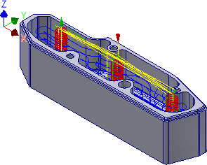
Continue to To Drill the Threaded Holes...