Workflow:
- To mark the position of the thread profile, create work planes.
- Create the profile.
- Cut the threads
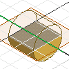
Create cylinder and work features to position threads
Place the work features on the cylinder center, perpendicular to the cylinder end.

- Create a profile using commands on the Sketch tab.
- On the 3D Model tab, Create panel, click Extrude to extrude the profile into a cylinder.
- In the browser, click the Origin icon, select the default work planes, right-click, and click Show. Or:
- To specify a work axis on the center point, on the 3D Model tab, Work Features panel, use Axis.
- To create a work plane perpendicular to the end of the cylinder, on the 3D Model tab, Work Features panel, use Planar.
Create and position profile for threads
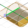
Create a sketch plane on the work plane, perpendicular to the end of the cylinder.

- Sketch the thread profile.
- Project the silhouette of the cylinder, the top or bottom edge of the cylinder, and the work axis to the sketch plane.
- To position the profile shape relative to the cylinder, constrain it, and add dimensions. Usually the profile is offset from the end of the cylinder so that threads are positioned correctly at the top of the cylinder.
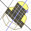
Create threads

To begin, sketch a profile that represents the cross section of the coil feature. Then, use the Line command, or the Work Axis command to create an axis of revolution for the coil.
- On the ribbon, click 3D Model tab
 Create panel
  Coil
Coil  .
. - Select the profile.
- Click the axis of revolution.
- Under Operation, select Cut.
- Click the Coil Size tab, then click the down arrow on the Type box, and then select one of the following Types:
- Pitch and Revolution
- Revolution and Height
- Pitch and Height
- Enter values to define the coil type.
- Click the Coil Ends tab. Then, to define the start and end of the coil, choose a method:
- To taper the ends of the coil, click Flat. Enter a Transition Angle, and then a Flat Angle.
- To end the coil without taper, click Natural.