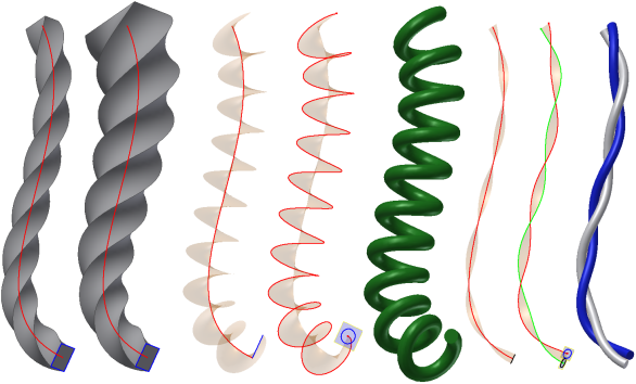
Sweep features or bodies are created by moving or sweeping one or more sketch profiles along a path. The multiple profiles you use must exist in the same sketch. The path can be an open or closed loop, but must pierce the profile plane.

A sweep feature usually requires a minimum of two unconsumed sketches , a profile and a path, on intersecting planes. In some cases, you can use a single unconsumed sketch for the profile and an existing model edge for the path. To control orientation of the swept profile, you can hold the profile constant to the path, or parallel to the original profile. To control scale and/or twist of a swept profile, select a guide surface or guide rail.

For a perpendicular sweep created in Inventor 2015 or later, you can use the twist option to enter an angle to control twist as the profile sweeps along the path.

In the assembly environment, only the solid output with a cut operation is available. The join, intersect, and New body operations are not supported. Only 2D sketches are allowed for assembly features so you cannot select feature edges as a sweep path.
Traditional path sweeps are used for objects that have uniform profiles swept along a trajectory, such as gasket grooves and cabling or piping through an assembly.
Guide rail sweeps are used for objects that have nonuniform profiles that scale or twist along a trajectory, such as a complex handle for a consumer part.
Guide surface sweeps are used for objects that have uniform profiles swept along a nonplanar trajectory. The twist of the profile must maintain a given orientation to a selected surface, such as a machining operation on a cylindrical part.