How To ... Develop An SVG Polygon Renderer - Part 3
| How To > Develop An SVG Polygon Renderer - Part 3 |
The following is part three of a three parts tutorials series demonstrating the use of MAXScript together with the Vector_Map TextureMap. MAXScript will be used to write an SVG XML file to disk containing polygon entities representing the faces of scene objects to be rendered. The SVG file can be loaded in any Web Browser or rendered to a bitmap via the renderMap() function. For more information about the use of MAXScript to create SVG files, please see the Vector_Map TextureMap and MAXScript topic.
In the first part of the tutorial, we output all camera-facing triangle faces of all geometry object.
In the second part of the tutorial, we sorted the polygons by depth to make sure the faces do not overlap incorrectly.
In this third part of the tutorial, we will add support for material colors and implement lighting using Facets Shading and Blinn Specular Highlights.
Vector_Map TextureMap and MAXScript
Step-By-Step
(
fn ColorToHex col =
(
	local theComponents = #(bit.intAsHex col.r, bit.intAsHex col.g, bit.intAsHex col.b)
	local theValue = "#"
	for i in theComponents do
		theValue += (if i.count == 1 then "0" else "") + i
	theValue
)

fn compareFN v1 v2=
(
	if v1[6] < v2[6] then -1 else 1
)

local st = timestamp()
local theFileName = (getDir #userscripts + "\\PolygonRendering8.svg")
local theSVGfile = createFile theFileName
format "<svg xmlns=\"http://www.w3.org/2000/svg\"\n" to:theSVGfile
format "\t\txmlns:xlink=\"http://www.w3.org/1999/xlink\">\n" to:theSVGfile

local theViewTM =  viewport.getTM()
theViewTM.row4 = [0,0,0]
local theViewTM2 = viewport.getTM()
local theViewPos = (inverse (viewport.getTM())).row4
In order to calculate the shading, we will need to compute the view ray connecting the eye (camera position) with the center of the face.
Even when there is no explicit camera, the fourth row of the inverted view transformation matrix gives us the viewer's location.
local theViewSize = getViewSize()
local theViewScale = getViewSize()
theViewScale.x /= 1024.0
theViewScale.y /= 1024.0

local drawArray = #()

local theStrokeThickness = 1

gw.setTransform (matrix3 1)
local theLights = for o in Lights where classof o != TargetObject collect o
for o in Geometry where not o.isHiddenInVpt and classof o != TargetObject do
(
	local theStrokeColor = o.wirecolor
	if classof o.material == StandardMaterial then
	(
		local theFillColor = o.material.diffusecolor
		local theSpecularPower = o.material.Glossiness
		local theSpecularLevel = o.material.SpecularLevel/100.0
	)
	else
	(
		local theFillColor = o.wirecolor
		local theSpecularPower = 50.0
		local theSpecularLevel = 0.25
	)
We will now change the Stroke color to be taken from the object's wirecolor property.
The Fill color will be set to the diffuse color of the material if a Standard Material is assigned to the object, otherwise the wirecolor will be used again.
Additionally, we will try to get the SpecularPower (Glossiness) value and the SpecularLevel of the Standard Material to reflect correctly the shading parameters.
Note that the 3ds Max UI exposes the Specular Level as 100 times stronger to make it easier to control, so we have to divide it by 100.0 to bring it in the right range.
If there is no Material, we will set the specular settings to be very close to what the 3ds Max viewports use in that case...
local theMesh = snapshotAsMesh o
	for f = 1 to theMesh.numfaces do
	(
		local theNormal = normalize (getfaceNormal theMesh f)
		if (theNormal*theViewTM).z > 0 do
		(
			local theFace = getFace theMesh f
			local v1 = gw.transPoint (getVert theMesh theFace.x)
			local v2 = gw.transPoint (getVert theMesh theFace.y)
			local v3 = gw.transPoint (getVert theMesh theFace.z)

			v1.x /= theViewScale.x
			v1.y /= theViewScale.y
			v2.x /= theViewScale.x
			v2.y /= theViewScale.y
			v3.x /= theViewScale.x
			v3.y /= theViewScale.y

			local theFaceCenter = meshop.getFaceCenter theMesh f
			local theZDepth = (theFaceCenter*theViewTM2).z
local theViewVector = normalize (theViewPos - theFaceCenter)
For the shading calculations, we will need the normalized view vector pointing from the center of the face at the viewer's position.
local theLitFillColor = black
We will initialize a new variable to black color.
This will be the variable where we will accumulate the lighting information as we process the lights and shade the face.
We could initialize this value to the Ambient color of the material if we want to support Ambient lighting.
			for aLight in theLights where classof aLight != TargetObject do
			(
				local theLightVector = normalize (aLight.pos - theFaceCenter)
				local theHalfVector = normalize (theLightVector + theViewVector)
A for loop will visit all light sources in the scene.
For each light, we will calculate the light vector (a normalized vector pointing from the center of the face at the light).
We will also calculate the Half-Vector (according to the Blinn Shading approximation of the Phong Shading model) by adding the Light Vector and the View Vector.
 				theDiffuse = (dot theLightVector theNormal)
				if theDiffuse < 0 do theDiffuse = 0
The Diffuse component is calculated as the dot product of the Light Vector and the Normal. It is view-independent (because the diffusion is Isotropic, the same in all directions).
The amount of light diffused depends only on the cosine of the angle between the Light Vector and the Normal.
Faces pointing away from the light get no light at all, so when the dot product is negative, we set the value to 0.
 				theSpecular = (dot theNormal theHalfVector)
				if theSpecular < 0 do theSpecular = 0
				theSpecular = (theSpecular^theSpecularPower)*theSpecularLevel
The Specular component on the other hand is view-dependent.
We calculate the dot product of the Normal and the Half Vector which depends on the Light Vector and the View Vector.
Again, we don't want any influence on faces that are facing in the opposite direction, so we zero out any values below 0.
The actual specular value is then taken to the power of the Glossiness (a.k.a. SpecularPower), and multiplied by the Specular Level.
				theLitFillColor += theFillColor * aLight.color * theDiffuse + aLight.color * theSpecular
			)--end aLight loop
The influence of the light will be accumulated into the variable we originally initialized to black.
The value that is added is comprised of the fill color multiplied by the light color, multiplied by the Diffuse coefficient.
To that we add the light color multiplied by the Specular coefficient.
This is repeated for all lights, producing the combined illumination of the face.
			if theLitFillColor.r > 255.0 do theLitFillColor.r = 255
			if theLitFillColor.g > 255.0 do theLitFillColor.g = 255
			if theLitFillColor.b > 255.0 do theLitFillColor.b = 255
Finally we want to clamp the color to 255 to avoid strange results because the Hexadecimal conversion does not support Hight Dynamic Range colors.
append drawArray #(v1, v2, v3, (ColorToHex theStrokeColor), (ColorToHex theLitFillColor), theZDepth)
We just have to change the name of the Fill Color variable to include the lighting in the array.
							)
	)--end f loop
)--end o loop
qsort drawArray compareFN

for d in drawArray do
(
	format "\t<polygon points='%,%  %,%  %,%' \n" d[1].x d[1].y d[2].x d[2].y d[3].x d[3].y to:theSVGfile
	format "\tstyle='stroke:%; fill:%; stroke-width:%'/>\n" d[4] d[5] theStrokeThickness to:theSVGfile
)

format "</svg>\n" to:theSVGfile
close theSVGfile
local theSVGMap = VectorMap vectorFile:theFileName alphasource:0
local theBitmap = bitmap theViewSize.x theViewSize.y
renderMap theSVGMap into:theBitmap filter:true
display theBitmap
format "Render Time: % sec.\n" ((timestamp()-st)/1000.0)
)
Using The Script To Render Geometry And Lights
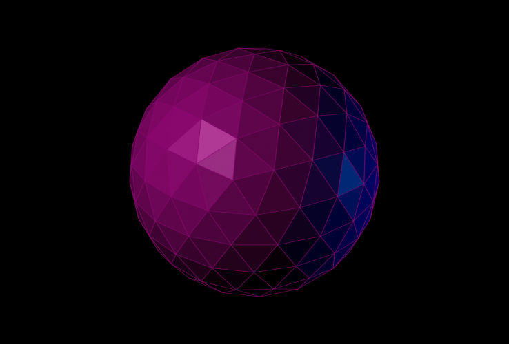
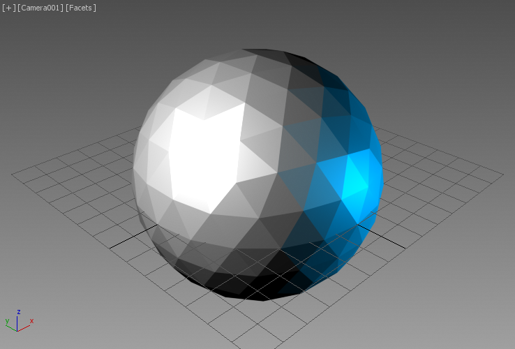
Let's render once again the same Geosphere as before, but this time lit by two Omni lights - one white on the left, and one blue and with a lower Multiplier on the right.
The left image is the screenshot of the viewport set to Facets + Edged Faces mode. The right image shows the render output of our SVG script:


Let's see how this changes when we assign a default Standard Material to this object.
The Fill color of the faces will now be taken from the Diffuse color of the material, while the Stroke color will be taken from the .wirecolor property:


The default Standard Material has a Specular Level of 0, so there is no Specular component in the above rendering.
Let's increase the Specular Level to 100, and change the Glossiness to 20.


It is very easy to modify the script to render without edged faces - simply set the edge color to the lit fill color!
append drawArray #(v1, v2, v3, (ColorToHex theLitFillColor), (ColorToHex theLitFillColor), theZDepth)
As you can see, our script's output matches very closely the representation of the same object in the viewport:


