Move Tool, Rotate Tool, Scale Tool
These menu items act the same as clicking the Move Tool, Rotate Tool, or Scale Tool in the Tool Box.
Universal Manipulator
This menu item is the same as clicking the Universal Manipulator in the General shelf.
Move Normal Tool
Use the Move Normal Tool to move selected CVs on a NURBS surface in the U or V direction of the surface. This is the same as selecting the Normal option for the Move Tool.
The Update [UVN] Triad check box is turned on by default.
All other settings are the same as the Move Tool.
Move/Rotate/Scale Tool
Shows the move, rotate, and scale handles in one manipulator.
Show Manipulator Tool
Shows a manipulator tailored for the selected node or attribute. See Show Manipulator Tool.
Default Object Manipulator
These items let you use the Move, Rotate, or Scale manipulators with the Show Manipulator Tool instead of the custom manipulator for a node.
Select None to show the node’s custom manipulator, rather than a transform manipulator. This is the default.
This information is saved with the scene. It is also shown in the Attribute Editor in the Display section of the Transform node.
Proportional Modification Tool
Lets you move components based on their distance from a manipulator.
Modification type
- World
-
Proportional modification happens in XYZ space.
- Parametric (NURBS)
-
Proportional modification happens in UV space.
Modification Falloff: Linear
This is the default modification falloff. Maya performs the modification in a linear fashion and displays the Distance Cutoff option.
- Distance Cutoff
-
Objects further away than this value are ignored. The distance is measured in 3D from the manipulator handle. For Parametric (NURBS) modification type, you set Distance Cutoff U and Distance Cutoff V.
- Distance Based On
-
The distance from the manipulator handle to the object directly influences the modification factor. The distance is computed along the selected axes only. If any of these is turned off, the distance used in the computation of the propmod effect from the handle to the point ignores that component.
Modification Falloff: Power
Using the Proportional Modification Tool, you can set the degree to any value between +5 and -5 and the falloff is non-linear (it forms a logistic curve). However, if you set the degree to 1, the falloff is linear again.
- Distance Cutoff
-
Objects further away than this value are ignored. The distance is measured in 3D from the manipulator handle. For Parametric (NURBS) modification type, you set Distance Cutoff U and Distance Cutoff V.
- Degree
-
Specifies the degree of effect in the U and V directions. A value of 0 applies the transformation equally over the entire region.
A positive value decreases the effect of the transformation for objects further away from the manipulator handle; the greater the degree, the greater this dampening effect.
If Degree is negative, the effect of the transformation is increased for objects further away from the manipulator handle.
- Distance Based On
-
The distance from the manipulator handle to the object directly influences the modification factor. The distance is computed along the selected axes only.
Modification Falloff: Curve
This option uses an animation curve to create the falloff. An animation curve profile can be used to produce a modification factor.
- Anim. Curve
-
Enter the name of an existing animation curve. Its vertical direction maps into the modification factor. The distance maps to the anim curve time axis (in seconds).
You can use the drop-down list to the right of the box to list and select all the anim curves with names starting with propModAnimCurve. You can also create one of those by choosing Create New from the same drop-down list.
- Scale U, Scale V
-
For Parametric (NURBS) Modification type only.
- Distance Based On
-
The distance from the manipulator handle to the object directly influences the modification factor. The distance is computed along the selected axes only.
Modification Falloff: NURBS Curve
For World Modification type only. This option uses a NURBS curve to create the falloff. A NURBS curve profile can be used to produce a modification factor.
Enter the name of an existing NURBS curve. Its vertical direction maps into the modification factor. The distance maps to the NURBS curve.
You can use the drop-down list to the right of the box to list and select from all the NURBS curves.
Soft Modification Tool
Lets you modify a surface by smoothly pulling or pushing groups of vertices.
- Falloff Radius
-
Determines the area of deformation by the soft modification tool. The area defined by the radius is dependent on the Falloff Mode and whether the Falloff Around Selection option is turned on.
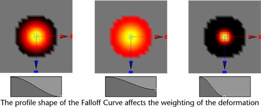
- Falloff Curve
-
Controls the weighting of the deformation within the area defined by the Falloff Radius. The default shape of the Falloff Curve specifies more influence at the centre of the selection area and less influence at the outer edges of the region of deformation. The shape of the Falloff Curve can be manually adjusted depending on the desired results.

Falloff Mode
Determines how the deformation will occur for the selected region.
- Volume
-
When the Falloff Mode is set to Volume, the soft modification is based on a 3D volume of a sphere that gets positioned about the centre of the region of influence.
- Surface
-
When the Falloff Mode is set to Surface, the soft modification is based on a region that conforms to the contours of the surface. Surface mode is useful when you want the soft modification deformation to wrap on a surface. For example, you can separate the upper lip from the bottom lip on a characters face using the surface-based falloff mode.
- Preserve History
-
When Preserve History is on, all nodes that the Soft Modification Tool creates are maintained. If you want to animate the effect of the soft modification deformer or modify deformation attributes later on, you’ll need to turn on Preserve History to ensure the deformation history is maintained.
When Preserve History is off, the Soft Modification Tool attempts to remove the deformation history and all additional nodes that it creates. If you are using Soft Modification as a modeling tool, and do not want modeling history, you should turn off Preserve History.
Note:In order to generate the correct result, the Soft Modification Tool can only delete deformation history when the underlying shape does not have existing history. If deformer history nodes are still created even when Preserve History is off, try deleting history on the target shape and then try deforming it again.
- Mask Unselected
-
When Mask Unselected is turned off all components are deformed. When Mask Unselected is turned on only selected components are deformed.
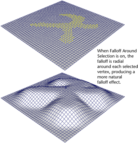
Falloff Around Selection
Select from the following options:
- on
-
The falloff is radial around each selected vertex. This can produce a more natural falloff effect, especially when the selected vertices form an arbitrary shape.
- off
-
The falloff is spherical around the center of the selection.

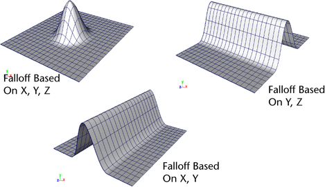
- Falloff Based On
-
The direction(s) along the X, Y, or Z axes in which the deformation falloff curve is applied. By turning off falloff along one or more directions, you can create various effects (for example, ramps, edges).

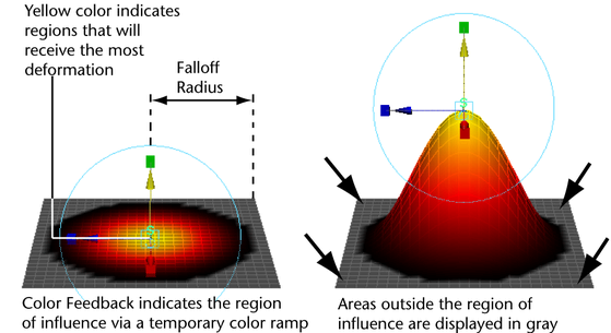
- Color Feedback
-
When Color Feedback is turned on the surface mesh is temporarily shaded with a color ramp in the area influenced by the soft modification deformer. The color ramp temporarily replaces the assigned shading material whenever the soft modification manipulator is active.
Color Feedback provides a visual indication of the region of influence as well as the amount of influence and falloff within the affected region. Areas that receive the most influence (based on shape of the Falloff Curve) appear in yellow. The color ramp blends to a darker orange/red as the influence of the deformer diminishes. Regions that fall within the area of influence but are not deformed appear as black. Regions outside of the Falloff Radius appear as a gray color.
Color Feedback appears on polygonal surfaces in either wireframe or shaded modes. Color Feedback appears on NURBS surfaces in shaded mode only and is not supported for subdivision surfaces.
You turn the Color Feedback display on or off using the setting in the Soft Modification Tool Settings editor.

Notes
- Soft Modification works like a deformer in that it controls a set of points (CVs, vertices) with a varying degree of influence that you can specify.
- Soft Modification produces a separate softMod node to produce the transformation, which can be animated.
- If the Mask Unselected and Falloff Around Selection options are turned on simultaneously, the selected vertices will move similar to a Move Tool operation on the vertices. That is, only the selected vertices will be moved, and no falloff will occur because of the masking that occurs.
- The Soft Modification Tool is similar to the Transformation Tools' Proportional Modification Tool. However, the Soft Modification Tool provides history and more control (for example, over falloff and color feedback). The Proportional Modification Tool only works on components. The Soft Modification Tool works on components, objects or multiple objects. The Proportional Modification Tool only works on multiple NURBS surfaces. The Soft Modification Tool works on multiple surfaces of any surface type. The Soft Modification Tool can be used with the Edit Deformers > Edit Membership Tool.