Define the size of the mold taking into account the requirements of the model.
If you have already completed the Initial configuration tutorial, you can access this study by opening the Speedo tutorial project you created. Alternatively, open a new project, name it Speedo tutorial, import the speedo_initial.sdy from the tutorial file (typically C:\Users\Public\Public Documents\Autodesk\Simulation Moldflow Adviser xxxx\tutorials ) and rename it Speedo_single.
To specify the mold dimensions do the following:
- Click on the Speedo_single study to open it.
- Click
 to open the Geometry tab.
 - Click
 . The Mold Properties pane appears. By default the mold is 25% bigger than the cavity. This is shown by the value entered in the Symmetric % text box. This needs to be modified to reflect the required mold dimensions.
 - Select the Symmetric check box.
- Enter 40 in the Symmetric text box and click Apply.
- Click
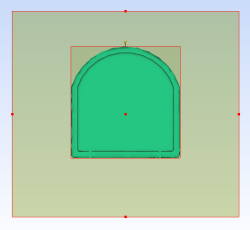
 to display the entire mold. The mold outline has been adjusted with an even border around the cavity.
 The flat sides of the model have holes in them. To mold these features, moving slides would need to be incorporated into three sides of the mold. Both sides (X direction) of the mold and the side of the mold opposite the injection location (negative Y direction) need extending to 50mm from the cavity. The injection side of the mold needs to be 30mm wide.
- Clear the Symmetric check box. The Offset coordinate fields are now editable.
- Enter the following values in the Offset coordinate fields:
Cell Wall width (mm) -X 50 +X 50 -Y 50 +Y 30 - Click Apply. The mold offset defines the length and width of the mold.
- Click to display the entire mold.
The mold outline has now been defined. You will now adjust the thickness of the plates.
- Using the
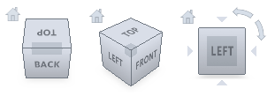 ViewCube click Bottom view.
 - Enter 95 in the A Plate thickness text box.
- Enter 30 in the B Plate thickness text box.
Note: The grade of metal the mold is to be made from can also be specified in this pane. This will affect the heat transfer calculations of any analyses.
- Click Apply.
The mold dimensions have been fully defined. In the next task you will create the sprue.