To simulate the effect that a load would have on post-molding part stresses, you can set an edge load on the model.
Loading conditions are applied in a global coordinate system by default; however, it is often preferable to use a local coordinate system to simplify the load to one direction. The following topic describes edge loading using the global coordinate system and a local coordinate system.
Global Coordinate System
A simple example of a surface edge load acting in a global direction is shown in the following image.
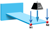
The edge is defined by points N1 and N2. A load of, for example, 0.5 N/mm is applied in the negative Z direction, to the nodes along this edge.
Local Coordinate System
An example of an edge load acting in a local direction (in this case a traction) is shown in the following image.
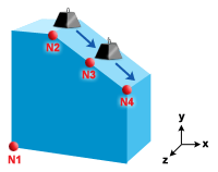
If the force is not perpendicular to the surface, and does not act in a global direction, you need to define and activate a local coordinate system at a selected node in the model before applying the local edge load.