An edited mesh might accidently result in a surface node being merged onto the opposite face of the model. This is called a collapsed surface.
A model with a collapsed surface is detected with the Mesh Repair Wizard:  ().
().
Description
The 3D model is made up of a mesh of multiple elements, called tetrahedron (tetra), through the thickness of the part (See Figure 1 below). There are internal nodes distributed between node A and B
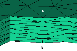
Normal mesh
Manual editing might accidentally result in node A and all the internal nodes between A and B being merged to node B on the bottom surface. The local area will look like Figure 2 below. The thickness at node B is actually zero. When this occurs, we say that the mesh is collapsed at node B
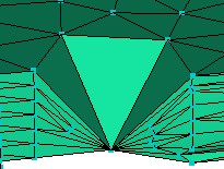
Collapsed mesh
A 3D analysis will run on a mesh containing collapsed (surface) elements, however the accuracy of the results will be impacted. The impact will be most significant on melt flow results and analyses that rely on the flow for their outcome (fiber orientation, weld lines, air traps)
Impact on the analysis
Collapsed surfaces can cause a distorted flow pattern as the solver interprets collapsed surfaces as holes or solid sections in the cavity that the melt must flow around. Analysis results for a mesh containing one or more pinhole-like collapse may not be as obvious as results from a mesh with multiple adjacent element/surface collapses. As collapsed elements primarily impact on flow predictions, collapsed elements/surfaces can also lead to the incorrect prediction of weld lines, air traps and fiber direction.
Recommended action
Collapsed elements/surfaces, particularly those furthest from the last point to fill, need to be repaired