To simulate the effects that an increase in temperature has on part stresses, you can set a thermal load on the model.
Thermal loading
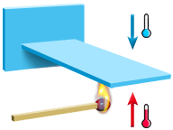
Thermal loads can be applied to selected elements in a model, in either in °C or °F. The thermal load is expressed as the difference in temperatures on the top and bottom sides of the selected elements. The top and bottom sides of mesh elements are defined by the orientation of the mesh. The top side of an element faces in the positive direction of orientation and the bottom side faces away from the orientation direction.
Apply thermal loads to models to simulate a real molding scenario. If you expect certain surface(s) inside the mold to experience increased temperatures, then simulated this by applying a thermal load to the appropriate part model surface(s).
A simple example of a thermal load is shown in the picture below. In this case, a thermal load (temperature increase) of, for example, 30°C is applied to the bottom side of the surface.