Composite materials are used only for the shell and membrane elements. To properly enter the material properties, the material axes must be defined in the Element Definition dialog. (See the pages Shell Elements and Membrane Elements.)
When the Material column is clicked on the Element Definition's Composite Laminate Stacking Sequence table, the Material Selection dialog shown in Figure 1 appears. The drop-down shows a list of all the composite materials that have been used for any lamina (ply) in any part of the model. Selecting an existing material and clicking the OK button will apply the chosen material to the current lamina.
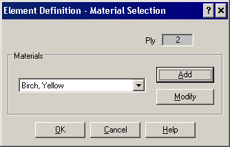
Figure 1: Material Selection for Composite Elements
When the Add button is clicked, the standard material library interface will appear. Choose a material from an existing library, or choose [Customer Defined] and enter custom properties. This will add a new material to the list of composite materials available for the model. If you choose a material and edit the properties, you can enter a Name which will appear in the drop-down box. Note that this name (and associated properties) are not used outside of the composite element material selection.
When the Modify button is clicked, the standard material library interface also appears, from which an existing material can be selected, or a [Customer Defined] material can be used. The difference between Modify and Add is that the original material selected in the drop-down is replaced (or updated) with the new properties entered when the Modify button is used.
The composite material properties are listed below. Depending on the element type and options, not all the material properties may be required. In addition to the properties listed below, it may be necessary to define some Isotropic Material Properties.
Symbols used throughout this section are defined as follows:
| Ef | modulus of elasticity of the fiber material |
| Em | modulus of elasticity of the matrix material |
| Gf | shear modulus of elasticity of the fiber material |
| Gm | shear modulus of elasticity of the matrix material |
| μ f | Poisson's ratio of the fiber material |
| μ m | Poisson's ratio of the matrix material |
| Vf | fraction of total volume taken up by the fiber material |
| Vm | fraction of total volume taken up by the matrix material (= 1 - Vf) |
Elastic Properties
- Modulus of Elasticity Local Axis 1 (E1): The modulus of elasticity for local axis 1 is the slope of the stress versus strain curve of local axis 1 of a material until the proportionality limit. This is also referred to as the Young's modulus of local axis 1. Also, for a fibrous composite material the following equation may be used: E1 = Vf*Ef + Vm*Em where the properties are in the direction of local axis 1.
- Modulus of Elasticity Local Axis 2 (E2): The modulus of elasticity for local axis 2 is the slope of the stress versus strain curve of local axis 2 of a material until the proportionality limit. This is also referred to as the Young's modulus of local axis 2. Also, for a fibrous composite material the following equation may be used: E2 = Vf * Ef + Vm * Em where the properties are in the direction of local axis 2.
- Poisson's Ratio Local Plane 12 (Major) (µ12): The Poisson's ratio for local plane 12 is found by taking the negative lateral strain in the local plane 12 and dividing it by the axial strain in the direction normal to the local plane 12 for an axially loaded member. (µ12 = -strain direction 2/strain in direction 1) Typical values for Poisson's ratio range from 0.0 to 0.5. For a fibrous composite the following equation can be used: μ12 = Vf * µf + Vm * μm where the properties are measured in the 12 plane. Poisson's ratio for local plane 12 can be referred to as the major Poisson's ratio.
- Shear Modulus of Elasticity Local Plane 12 (G12): The shear modulus of elasticity of local plane 12 (in the plane of the element) is the slope of the shear stress versus shear strain of plane 12 of a material until the proportionality limit. This is also referred to as the modulus of rigidity. For a fibrous composite the following equation can be used: G12 = (Gf * Gm) / (Vm * Gf + Gm * Vf)
- Shear Modulus of Elasticity Local Plane 13:The shear modulus of elasticity of local plane 13 (perpendicular to the element) is the slope of the shear stress versus shear strain of plane 13 of a material until the proportionality limit. This is also referred to as the modulus of rigidity. This property is only applicable to shell elements.
- Shear Modulus of Elasticity Local Plane 23:The shear modulus of elasticity of local plane 23 (perpendicular to the element) is the slope of the shear stress versus shear strain of plane 23 of a material until the proportionality limit. This is also referred to as the modulus of rigidity. This property is only applicable to shell elements.
Allowable Stresses
The allowable stresses are required if a Tsai-Wu or Maximum Stress failure criteria is specified. Refer to the pages Shell Elements and Membrane Elements for the selection of the failure criteria and the equations that govern failure.
- Compressive Stress of Local Axis 1 (Xc): The allowable compressive stress of local axis 1 is a material property that is used in different failure criteria for a composite element analysis. Note that a positive value needs to be entered.
- Tensile Stress of Local Axis 1 (Xt): The allowable tensile stress of local axis 1 is a material property that is used in different failure criteria for a composite element analysis.
- Compressive Stress of Local Axis 2 (Yc): The allowable compressive stress of local axis 2 is a material property that is used in different failure criteria for a composite element analysis. Note that a positive value needs to be entered.
- Tensile Stress of Local Axis 2 (Yt): The allowable tensile stress of local axis 2 is a material property that is used in different failure criteria for a composite element analysis.
- Shear Stress of Local Plane 12 (S): The allowable shear stress of the local 12 plane is a material property that is used in different failure criteria for a composite element analysis.
- Stress interaction F12 (Tsai-wu): The stress interaction F12 is a failure criteria property that is used only for the Tsai-Wu failure theory. It is determined from biaxial tests. If no value is entered, then the following equation will be used: where F11 = 1/(Xt*Xc) and F 22 = 1/(Yt*Yc). For numerical stability, this condition must be satisfied:
Allowable Strains
The allowable strains are required if the maximum strain failure criteria is specified. Refer to the pages Shell Elements and Membrane Elements for the selection of the failure criteria and the equations that govern failure.
- Compressive Strain of Local Axis 1 (T1c ): The allowable compressive strain of local axis 1 is a material property that is used in different failure criteria for a composite element analysis. This property is applicable to both types of composite elements. Note that a positive value needs to be entered.
- Tensile Strain of Local Axis 1 (T1t ): The allowable tensile strain of local axis 1 is a material property that is used in different failure criteria for a composite element analysis. This property is applicable to both types of composite elements.
- Compressive Strain of Local Axis 2 (T2c ): The allowable compressive strain of local axis 2 is a material property that is used in different failure criteria for a composite element analysis. This property is applicable to both types of composite elements. Note that a positive value needs to be entered.
- Tensile Strain of Local Axis 2 (T2t ): The allowable tensile strain of local axis 2 is a material property that is used in different failure criteria for a composite element analysis. This property is applicable to both types of composite elements.
- Shear Strain of Local Plane 1-2 Plane (S): The allowable shear strain of the local 12 plane is a material property that is used in different failure criteria for a composite element analysis. This property is applicable to both types of composite elements.
Flexure Controls
By default, the flexural properties will be calculated from the elastic properties. To use specific values for the flexural properties, activate the Flexural Modulus check box, and then enter the following properties. Since membrane elements do not have bending capability, the flexural input is applicable only to shell composite elements.
- Flexural Modulus of Local Axis 1: The flexural modulus of local axis 1 is the slope of the moment-curvature curve in the local 1 direction before the proportionality limit.
- Flexural Modulus of Local Axis 2: The flexural modulus of local axis 2 is the slope of the moment-curvature curve in the local 2 direction before the proportionality limit.
- Flexural Poisson's Ratio of Local Plane 12: The flexural Poisson's ratio is the ratio of the curvature in the local 1 direction to the curvature in the local 2 direction.
- Torsional Rigidity of Local Plane 12: The torsional rigidity of the local plane 12 is comparable to the shear modulus. If no value is provided, a value will be calculated using the flexural modulus and the flexural Poisson's ratio.
Temperature Dependent Composites
When the material model is set to Temperature Dependent Composite, the material properties are entered into a table. (Currently, only the Co-rotational Shell element has temperature-dependent composite materials.) Each row of the table gives the properties at a specific temperature. Use the Sort button as needed to sort the table by ascending temperature.
The input for the temperature-dependent properties is the same as described above (with the addition of the coefficient of expansion), but referred to by different labels. Here is the meaning of each column of input.
| Temperature Dependent Input | Equivalent Input Described Above |
|---|---|
| Index | The row number. (Automatically set by the software.) |
| Temperature | The temperature corresponding to the material properties entered on the row. |
| E1 | Modulus of Elasticity Local Axis 1 |
| E2 | Modulus of Elasticity Local Axis 2) |
| v12 | Poisson's Ratio Local Plane 12 (Major) |
| G12 | Shear Modulus of Elasticity Local Plane 12 ) |
| G13 | Shear Modulus of Elasticity Local Plane 13 |
| G23 | Shear Modulus of Elasticity Local Plane 23 |
| alpha1 | The thermal coefficient of expansion for local axis 1 is a property based on the contraction and expansion of the material. |
| alpha2 | The thermal coefficient of expansion for local axis 2 is a property based on the contraction and expansion of the material. |
| XC | Compressive Stress of Local Axis 1 |
| XT | Tensile Stress of Local Axis 1 |
| YC | Compressive Stress of Local Axis 2 |
| YT | Tensile Stress of Local Axis 2 |
| S | Shear Stress of Local Plane 12 |
| F12 | Stress interaction F12 (Tsai-wu) |