Many of the commands are identical to commands for linear results. Below are the commands that are unique to nonlinear analyses.
Concrete Failure
If the model includes a part set to the reinforced concrete material model, then the Results Contours  Other Results Concrete Failure command will be available. When selected, the model is shaded based on whether any of the integration points within the element have the following type of failure:
| Table 1: Concrete Failure Values | |
|---|---|
| Failure Value | Interpretation |
| 1 | at least one point has crack |
| 0.5 | at least one point has crushed but no cracking |
| 0 | no points have cracked or crushed |
- To see the values properly, make sure the Results Contours Settings Smooth Results is deactivated. Otherwise, different results in adjacent elements will affect the display.
- The colors are easier to distinguish if you set the Results Contours Settings Legend Properties Presets on the Contour Colors tab to Tri-color scheme and set the Tick Marks to 3 on the Legend Properties tab.
Although the Concrete Failure will quickly show whether any elements have failed, there is much more information about the failure available from the Results Inquire Inquire Current Results. When a failed element is selected (Quick Access Toolbar Select Elements), the following information can be included:
- The integration point at which the failure has occurred.
- The number of cracks at the integration point, if any.
- The status of the cracks, which can be either opened (cannot transmit a load) or closed (potentially transmitting a load, depending on the material properties).
- Up to three cracks can occur in mutually perpendicular planes. The crack direction gives the normal to the plane of the crack.
- Whether the integration point has been crushed. Note: In the reinforced concrete material model, crushing is defined as a failure state when all three principal stresses exceed the compressive allowable. All three principal stresses will be negative.
Stress Gasket
When the analysis includes gasket elements, the Results Contours Other Results Gasket Results contains a bump-out for Gasket results. By definition of the gasket elements, all the results pertain to the thickness direction (normal to the surface).
- Pressure shows the pressure in the gasket element.
- Overall Closure shows the distance that the top and bottom surfaces have moved closer together. A positive value indicates the gasket is thinner than the original position. This value is the same as the compression in the gasket material only when the gasket's Initial Gap is set to 0.
- Mechanical Closure shows the amount of compression in the gasket. This result corresponds to the Closure values entered in the material properties. It is different from the Overall Closure when the gasket's initial gap property is nonzero. The relationship is as follows: Mechanical Closure = Overall Closure - Initial Gap
- Accumulated Plastic Closure shows the amount of permanent deformation that has developed in the gasket.
Surface Contact
This option will only be available for a model with surface-to-surface contact defined. When this command is selected, the surfaces that are involved in the surface to surface contact will be shaded according to the distance between that surface and the other surface in that contact pair. For each node, the average normal will be calculated from all the faces of which that node is involved with. A line will be extended along this normal until it intersects the other surface. If the normal from any node on a face does not intersect the other surface, that face will not be shaded. For example if a node has penetrated the surface, the faces that contain that node will not be shaded.
Plasticity
This command will only be available if one of the parts of the model is using an elastic-plastic material model and the Additional output drop-down box in the Advanced tab of the Element Definition screen is set to any option except Not generated.
- Plastic State: If this command is selected, the legend box will range from a value of 0 to a value of 1. Any area that is shaded with the color corresponding to 0 is in the elastic state. Any area shaded with the color corresponding to 1 is in the plastic state. This contour is only valid for the present time step.
- Yield Stress: If this command is selected, the model is shaded with the yield stress set as the lower limit. Anything below the yield stress is shaded with the color corresponding to the lowest value in the legend box.
- Equivalent Stress: If this command is selected, the model is shaded with the equivalent (or effective) stress. This stress value includes the effect of the size of the yield surface for the calculations. In Autodesk Simulation Mechanical, equivalent stress for the
von Mises with Kinematic Hardening
and the
von Mises Curve with Kinematic Hardening
material models is defined as:
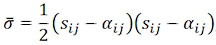
where sij is the stress deviator tensor and αij is the back stress tensor. Following this definition, the value of equivalent stress could be significantly different from the von Mises stress value for the same point.
- Equivalent Strain: If this command is selected, the model is shaded with the equivalent (or effective) strain increment. This is a scalar value equal to the magnitude of the plastic strain tensor. Note: Plasticity results are not available at midside nodes.
Damage
This command will be available when any of the parts of the model are used in the damage analysis (one of the damage options chosen on the Damage tab of the Element Definition dialog). The results of the damage analysis are as follows:
- Fiber: Tensile Criterion: Shade the model based on the tensile criterion in the fiber direction (fI).
- Fiber: Compressive Criterion: Shade the model based on the compressive criterion in the fiber direction (fII).
- Fiber: Tensile Damage: Shade the model based on the tensile fiber damage (dft).
- Fiber: Compressive Damage: Shade the model based on the compressive fiber damage (dfc).
- Matrix: Tensile Criterion: Shade the model based on the tensile criterion in the matrix direction (fIII).
- Matrix: Compressive Criterion: Shade the model based on the compressive criterion in the matrix direction (fIV).
- Matrix: Tensile Damage: Shade the model based on the tensile matrix damage (dmt).
- Matrix: Compressive Damage: Shade the model based on the compressive matrix damage (dmc).
- Damage Energy Density: Shade the model based on the damage energy density (ΔED). The damage energy density is a combination of all the damage in the element. A value of 0 indicates no damage has occurred. A low value indicates less damage than large values. Check the individual Damage results (Results Contours Other Results Damage Tensile Damage, and so on) to determine in which direction(s) the damage has occurred.
- Viscous Energy Density: Shade the model based on the viscous energy density (ΔEV). Since viscosity is added to the model to provide stability, the viscous energy density should be small compared to the damage energy density. Otherwise, the results may be affected by the user-supplied viscosity parameters.
- The Criterion result does not indicate whether damage has occurred. It represents whether (additional) damage can occur at a particular time step.
- For each Criterion result, a value of 1.0 or greater indicates that the initiation criterion has been met.
- The Damage result indicates how much damage has accumulated and has a range of 0 to 1. A value of 0 indicates no damage, and the element can support a full load. A value of 1 indicates complete damage, and the element cannot support any load in the respective direction.
- Damage results are not available at midside nodes.
Refer to the page Setting Up and Performing the Analysis: Nonlinear: Material Properties: Damage Material Properties: Damage Theoretical Description for additional details on each result.
Auxiliary Stress
Use this command for viewing what parts of the model are above initial yield stress and which are below yield. The value displayed is (calculated stress) - (yield stress). A negative value indicates no yield, a positive value indicates yield. This option is applicable only for 2D elements with a yielding criteria.