Place four of the previously created edge connector in an evenly spaced pattern in one direction.
- Click
 Home
Home  Solid Rectangular Pattern.
 - Expand the Edge Connectors:1 branch of the browser and select the Solid subheading.
- Click
 Pattern Selections Direction.
 - Click one of the short edges of the edge connector to indicate the pattern direction. Yellow and red direction arrows will appear.
- Click and drag the Y-direction arrow towards the opposite end of the circuit board. Note that the pattern defaults to three items in this direction, which we will change to four after specifying the pattern distance.
- Type 3.75 and press Enter to lock-in the dimension. The field indicating the number of items in the pattern for this direction will now be highlighted.
- Type 4 and press Enter. The field indicating the number of items in the pattern for the other direction will now be highlighted.
- Type 1 and press Enter, since we only want a 1x4 pattern of edge connectors.
- Press Enter once more to complete the Rectangular Pattern command.
- Click the Home icon (
 ) next to the ViewCube to return to the default isometric view. Note that this icon is not visible until the cursor is over the ViewCube area.
 - This completes the construction of the Circuit Board model. In the QAT, click
 Save. The model appears as shown below.
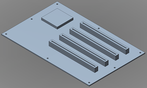
Normally, you could transfer the model immediately into Autodesk Simulation Mechanical by clicking  Home Simulation Simulation Mechanical. However, for the analysis that will follow, we must change the CAD import options for Simulation Mechanical. We will do that during the Mesh Circuit Board CAD Model tutorial. If you are going to proceed directly to this tutorial, leave Fusion running with the Circuit Board model loaded. Just minimize the Fusion window and proceed to the
Mesh Circuit Board CAD Model
tutorial.
Home Simulation Simulation Mechanical. However, for the analysis that will follow, we must change the CAD import options for Simulation Mechanical. We will do that during the Mesh Circuit Board CAD Model tutorial. If you are going to proceed directly to this tutorial, leave Fusion running with the Circuit Board model loaded. Just minimize the Fusion window and proceed to the
Mesh Circuit Board CAD Model
tutorial.
Otherwise, you can:
- Return to the main page of the Meshing and Modeling Tutorials.
- Go to the main page of the Analyzing and Evaluating Results Tutorials.