Hydrodynamic elements allow for the simulation of the interaction of fluids with solids without considering the details of the flow. These elements are only suited for well contained fluids, since the motion of the fluid (for example, sloshing) is not taken into account. Such interaction between fluid and solids is typically done using hydrostatic pressure loads. However, hydrodynamic elements provide for a much more accurate representation of fluid-solid interaction because they account for the inertia of the fluid when its container moves or deforms.
Hydrodynamic element follows the assumption that the shear stress is negligible and that strain energy is only dependents upon volumetric strain:
U = 0.5*K*ε v 2
where K and ε v are the bulk modulus and volumetric strain respectively. This gives a normal hydrostatic bulk response as P = K*ε v
2D hydrodynamic elements can be isoparametric quadrilaterals or triangular elements. Either geometrical type can have mid-side nodes. The quadrilateral elements have 4 nodes or 8 nodes if mid-side nodes are included; the triangular elements have 3 nodes or 6 nodes if mid-side nodes are included. Midside nodes are needed to better describe large scale motion of the fluid.
These elements are confined to the global YZ plane. The element can represent either planar (plane strain condition) or axisymmetric conditions. In both cases, each element node has two translational degrees of freedom (in Y and Z directions).
Select Types of 2D Hydrodynamic Elements
There are two types of 2D elements available for a nonlinear analysis. These can be selected in the Geometry Type drop-down box in the General tab of the Element Definition dialog.
- Axisymmetric: Select this geometry type for elements that model solids with geometric, load and boundary condition symmetry about the Z axis. Negative Y coordinates are not admissible. If a node lies along the axis of revolution (the Z axis) the translation in the Y direction must be constrained. Nodal loads are normalized by the number of radians in a circle (load divided by radians).

Figure 1: 2D Axisymmetric Model
- Plane Strain: Select this geometry type to model planar solids. A thickness of 1 unit is assumed; the setup of other parts in the model may need to be set appropriately to account for the hydrodynamic part. A thickness can be entered using the Thickness (visualization only) field, but this thickness is only used for the 3D visualization in the Results environment. (See the Browser Functions page.) All input loads and results are based on the 1 unit thickness.
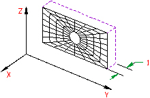
Figure 2: 2D Plane Strain
Control Orientation of 2D Hydrodynamic Elements
For a general FEA analysis, you can ignore the element orientation. The ability to orient elements is useful for elements with orthotropic material models and for easily interpreting stresses in local element coordinate systems. This is done in the Orientation tab of the Element Definition dialog. The Method drop-down box contains three options that can be used to specify which side of the element will be the ij side. If the Default option is selected, the side of an element with the highest surface number will be chosen as the ij side. If the Orient I Node option is selected, a coordinate must be defined in the Y Coordinate and Z Coordinate fields. The node on an element that is closest to this point will be designated as the i node. The j node will be the next node on the element traveling counterclockwise. If the Orient IJ Side option is selected, a coordinate must be defined in the Y Coordinate and Z Coordinate fields. The side of an element that is closest to this point will be designated as the ij side. The i and j nodes will be assigned so that the j node can be reached by traveling counterclockwise along the element from the i node.
Advanced 2D Hydrodynamic Element Parameters
Select the formulation method that you want to use for the 2D elements in the Analysis Formulation drop-down box in the Advanced tab. If the Material Nonlinear Only option is selected, nonlinear material model effects will be accounted for but all calculations will be performed based on the undeformed geometry. The Total Lagrangian option will refer to the initial undeformed configuration of the model for all static and kinematic variables. The Updated Lagrangian will refer to the last calculated configuration of the model for all static and kinematic variables.
Next, select the integration order that will be used for the 2D elements in this part in the Integration Order drop-down box. For rectangular shaped elements, select the 2nd Order option. For moderately distorted elements, select the 3rd Order option. For extremely distorted elements, select the 4th Order option. The computation time for element stiffness formulation increases as the third power of the integration order. Consequently, the lowest integration order which produces acceptable results should be used to reduce processing time.
For the 2D elements in this part to have the midside nodes activated, select the Included option in the Midside Nodes drop-down box. If this option is selected, the 2D elements will have additional nodes defined at the midpoints of each edge. This will change a 4-node 2D element into an 8-node 2D element. An element with midside nodes will result in more accurately calculated gradients. Elements with midside nodes increase processing time. If the mesh is sufficiently small, then midside nodes may not provide any significant increase in accuracy.
Basic Steps for Use of 2D Hydrodynamic Elements
- Be sure that a unit system is defined.
- Be sure that the model is using a nonlinear analysis type.
- Right-click the Element Type Tip: Useful commands for converting 3D models to 2D models are Draw
 Pattern Relocate & Scale, Draw Pattern Rotate or Copy, and Draw Modify Project to Plane. For example, you may accidentally create a mesh in the XY plane. You can rotate the mesh to the YZ plane using either the Relocate & Scale or Rotate command. Due to round-off, some nodes may have a small X coordinate value that prevents the element type from being set to 2D. In this case, use Project to Plane to snap the nodes exactly to the YZ plane.
 - Select the 2D Hydrodynamic command.
- Right-click the Element Definition heading.
- Select the Edit Element Definition command.
- In the General tab, select the appropriate geometry type in the Geometry Type drop-down box.
- Press the OK button.