Pipe elements are two-node members which allow arbitrary orientation in the 3D (three-dimensional) X, Y, Z space. The pipe transmits moments, torque and forces and is a general six degrees of freedom (DOF) element (for example, three global translation and rotational components at each end of the member).
The pipe element is a three-dimensional uniform cross-section element capable of being loaded by an internal pressure. The cross-section change of shape is not accounted for in any MES.
Externally, the pipe has six degrees of freedom -- three displacements and three rotations. The output from the analysis includes the end forces of the pipe, the axial stress and the associated shear stresses. It supports full 3D translation and rotation motions.
Pipe Element Geometry Types
The pipe element supports straight or curved geometry. For straight pipes, select the Tangent option in the Geometric type drop-down box in the General tab of the Element Definition dialog. For curved pipes, select the Bend option. The curves must be divided into lines in the actual model, but they will be analyzed using the curve geometry.
- Use Draw
 Draw Fillet to create the elbows or curved pipes. The Fillet command includes an option Create Pipe Bend which automates the input for curved pipe described below. Here's the ideal way to create elbows and curved pipe using the Fillet command with the Create Pipe Bend option:
 - Draw the piping model without the bends. Define all the properties of the straight pipe (Element Definition and Material properties) before creating the bends.
- Use Draw Draw Fillet to create the curved pipes. The controls on the pop-up are as follows:
- Part number will default to next available part number. The surface and layer numbers can be set by the user.
- Enter the radius of the bend in the Radius field.
- Since the curved pipe needs to be drawn as line segments, enter the number of segments with the Minimum Segments field. Since the analysis treats the fillet as the theoretical curved shape, one segment is sufficient for most applications.
- Activate the Create Pipe Bend option.
- Select the two lines to create a bend.
- Click the Apply button to generate the fillet and curved pipe elements. The parameters of the curve (center, radius) will be filled in the Element Definition.
- If the Element Definition of the straight sections of pipe is filled in, the parameters will be copied to the curved pipe's Element Definition (pipe diameter, wall thickness, and so on.) If the Material properties of the straight sections of pipe are defined, the material will be copied to the curved pipe's Material. Make any changes if necessary.
- If any change in the run is required in the Element Definition (different size of pipe, and so on), each bend needs to be changed.
Curved pipe geometry can be defined using two methods in the Geometry tab of the Element Definition dialog. You must first define the curve radius in the Radius of curvature of bend field. Next you must define a point in the X Coordinate, Y Coordinate, and Z Coordinate fields. If the Center of curvature option is selected in the Geometry of bend specified using drop-down box, this point must be the center point of the curve. If the Tangent intersection option is selected, this point must be the coordinates where the two straight sections of pipe would intersect without the bend. Before the analysis, a dimensional tolerance test will be performed on the end points of the lines that define the curve to verify that they are adequately close to the curve equation. They must be within the fraction of the wall thickness specified in the Tolerance field for the analysis to proceed.
The local directions for each element are different for each of the three geometric possibilities.
- The local 1 direction will lie along the length of the pipe.
- The local 3 direction will be defined by the cross product of the local 1 vector and the global Y axis. If the element is parallel to the global Y axis, the local three direction will be defined by the cross product of the local 1 vector and the global Z axis.
- The local 2 axis is defined as the cross product of the local 1 and 3 axes.
Straight Pipe:
- The local 2 direction is defined by the vector from the first endpoint of the arc to the center of curvature point.
- The local 3 direction is defined by the cross product of the local 2 direction and the vector from the second endpoint of the arc to the center of curvature point.
- The local 1 direction is the cross product of the local 2 and 3 axes.
Curved Pipe Specified with Radius and Center of Curvature:
- The local 1 direction is defined by the vector from the first endpoint of the arc to the tangent intersection point.
- The local 3 direction is defined by the cross product of the local 1 direction and the vector from the second endpoint of the arc to the tangent intersection point.
- The local 2 direction is the cross product of the local 1 and 3 axes.
Curved Pipe Specified with Radius and Tangent Intersection:
Other Pipe Element Parameters
The geometry of the pipe element cross-section must be defined using the Outside diameter and Wall thickness fields in the General tab of the Element Definition dialog. If you are performing a thermal stress analysis, specify the temperature at which no stress exists in the Stress free reference temperature field.
Advanced Pipe Element Parameters
You can specify the type of formulation that will be used for the pipe elements in the Analysis Formulation drop-down box in the Advanced tab of the Element Definition dialog. The Linear option will ignore nonlinear geometric effects that result from large deformation. The Geometrically nonlinear option will include these effects.
If the pipe elements contain a fluid, enter the mass of this fluid per unit length in the Nonstructural mass per length field. The mass of the pipe itself will already be calculated from the dimensions and the mass density entered in the material specification dialog. In many cases, using a Display Units system can make the input of mass easier than using the Model Units. See the page Converting Mass Units in the section General Options: Unit Systems for tips on converting the mass to the appropriate units.
If you do not want to account for any effects due to shear distortion during the analysis, select the Ignored option in the Shear distortions drop-down box. To specify a factor to account for shear distortions, selected the Included with user input shape factor option and specify the factor in the Shape factor field. The cross sectional area will be divided by this value and the quotient will be used as the effective shear area for both shear directions. For the shape factor to be calculated during the analysis, select the Included with automatically calculated shape factor option. The equation that will be used is
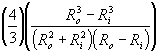
where R o is the outer radius of the pipe and R i is the inner radius of the pipe.
For the stress results for each element to be written to the text log file at each time step during the analysis, activate the Detailed stress output check box. This may result in large amounts of output.
Basic Steps for Use of Pipe Elements
- Be sure that a unit system is defined.
- Be sure that the model is using a nonlinear analysis type.
- Right-click the Element Type heading for the part that you want to be beam elements.
- Select the Pipe command.
- Right-click the Element Definition heading.
- Select the Edit Element Definition command.
- In the General tab, specify whether the pipe elements are straight, Tangent, or curved, Bend, in the Geometric type drop-down box.
- Specify the dimensions of the pipe cross-section in the Outside diameter and Wall thickness field.
- If you selected the Bend option in the Geometric type drop-down box, define the radius and center point or tangent point of the bend in the Geometry tab.
- Press the OK button.