When applying a voltage, a "stiffness" value must also be specified. This is a measure of the ability of the power source to maintain the requested voltage. If appropriate, voltage sag can be simulated by specifying a limited stiffness. For example, if the stiffness is 10 A/V and the current is 5 A, the applied voltage will be reduced by a 0.5 V (5/10).
In this example, we will use an arbitrary, high stiffness value of 1x10⁸ A/V, which will result in negligible voltage sag.
- With the cursor near the center of the motor, roll the mouse wheel to zoom in for a larger view of the hole through the center of the rotor.
- With the
 Selection
  Shape Point or Rectangle and
  Selection Select Surfaces commands active, click on the inside surface of this hole, as highlighted below (yellow on red), to select it.
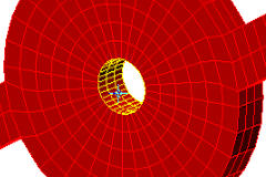
- Click
 Setup Loads Voltage.
 - Type 1e8 in the Stiffness field. We will leave the voltage at zero.
- Click OK.
- Click
 View Navigate Orientation Back View.
 - Click the face of the ring at the outside diameter of the motor, as highlighted below (yellow on green), to select it.

- Click Setup Loads Voltage.
- Type 15 in the Magnitude field.
- Type 1e8 in the Stiffness field.
- Click OK.