Create a solid model of the circuit board assembly shown below using Inventor Fusion. All dimensions are in inches:
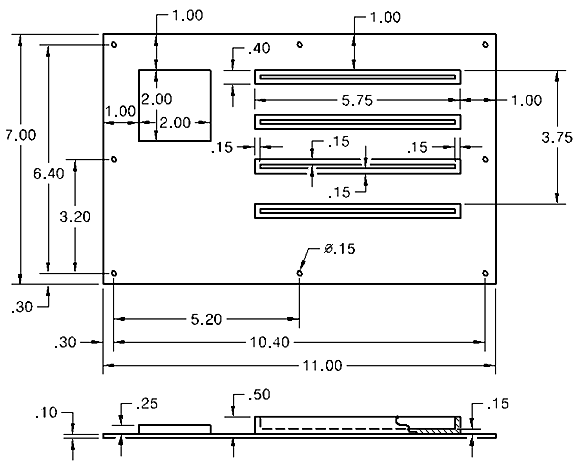
- The assembly consists of three parts—the board, the chip, and the edge connectors (all four connector bodies will be created as a single part using the Rectangular Pattern command).
- A single hole will be placed at a corner of the board and the remaining holes created by specifying a 3x3 rectangular pattern. One extraneous hole at the center of the board will be omitted from the 3x3 pattern, leaving only the eight holes shown in the above diagram.
- The Shell command will be used to hollow out the connector, leaving a wall thickness of 0.15 inch for the four sides and the bottom. The resulting slots will be 5.45 long x 0.1 wide x 0.35 deep.
- Use default material properties in Fusion for all three parts. The necessary thermal properties of the material will be defined within Autodesk Simulation Mechanical during the subsequent heat transfer analysis tutorial.