Using this dialog, you can define the method of dimensioning structure elements on drawings. Parametrization of the dimensioning lines is separate for the defined element views (view, section).
To display the Dimensioning layout dialog:
- On the Drawing templates manager dialog, for Drawing components, select Dimensioning
- Click New or Modify.
For Style name, enter a name for the component style, and click Save (this is only available when creating a style, not when modifying an existing style).
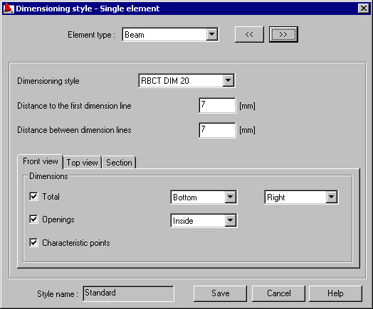
A selection list for selection of a structure element type (beam, column, spread footing, etc.) is located in the upper part of the dialog; it defines for which element the dimensioning parameters will be defined.
Design styles defined in AutoCAD® can be selected from the selection list. It is possible to set distance between the design lines in the edit fields.
On tabs related to the specified elements of view, it is possible to set location of the total dimension and, optionally, dimensions of openings and the characteristic points of an element.