Use this option to define styles of element dimensioning.
To begin defining styles, open the Dimensioning styles dialog from:
- Menu: Steel > Styles > Dimensioning styles
- Ribbon: ASD - Drawings > Settings > Dimensioning styles
- Command line: RBCS_DIM.
Dimensioning consists of positioning elements in a 2D projection of a position:
- Geometrical dimensions: linear dimensions of individual elements or elements joined together to create an element chain, arc dimensions, angle dimensions, diameters, and radial dimensions
- Symbols and names: weld symbols, bolt (opening) symbols, elevation marks, designations of assemblies and groups (profile types, positions), and so on
- Comments (additional text): variables describing created views and presented objects (name, scale, and so on), user-defined text
Dimensioning is performed automatically based on user-defined settings; it is also possible to modify created dimension lines and their descriptions. Dimensioning may be conducted within the edition contour. All dimensional elements (such as dimension lines, text style, and ends of dimension lines) are set in the dimension styles available in AutoCAD®.
You can define any number of dimensioning styles. Each defined style belongs to one of the categories concerning the type of a drawing position (single part, assembly, group, scheme - a group of elements constituting a structure model).
The dimensioning style defines:
- Dimension style from AutoCAD® to be applied
- Elements and the element projections in which the individual elements should be included
- Manner of arranging elements in the drawing
A set of defined styles is saved in a DWG format file or in a template (a DWT file).
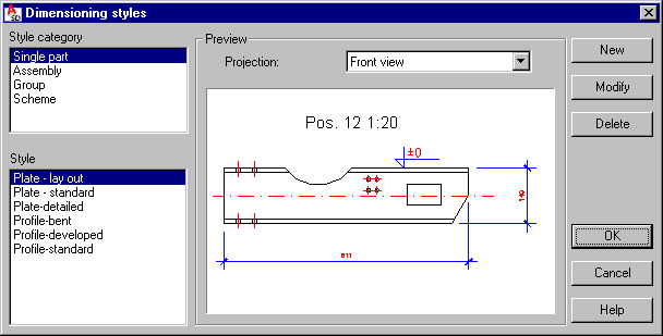
In the Dimensioning styles dialog, when a drawing position type is selected for Style, all defined styles for the selected category are displayed. A preview of a selected style is shown in the Preview field. For each style, there are different settings defined for each of available element views (top view, front view, side view, 3D view).
One of the styles defined for each drawing position type is a default style, and will be suggested as a default as you define a drawing template. The default type may be changed by highlighting a style within a given category and clicking Default.
Use the buttons on the right of the dialog:
New - click this to open the Dimensioning style settings dialog, where you can define a new style for a selected category. The name of a new style and all its settings are inherited from the style currently selected.
Modify - click this to open the Dimensioning style settings dialog, where you can change settings of a selected style.
Delete - click this to delete the style currently selected from the list of available styles for a given category.
See also: