At the top of the dialog, specify general parameters:
- ACAD dimension style - select an AutoCAD® dimensioning style that will be applied in the dimensioning style currently selected. The list contains all the dimensioning styles defined in a DWG format file
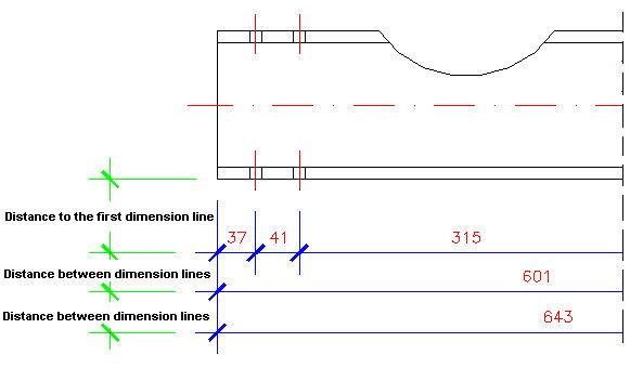
- Distance to the first dimension line - specify the distance between the edge of a dimensioned part and the first dimension line generated automatically
- Distance between dimension lines - specify the distance between successive dimension lines (see drawing below)
- Extension of axis beyond edge - specify the length that lines extend outside the element edges on both sides of the element
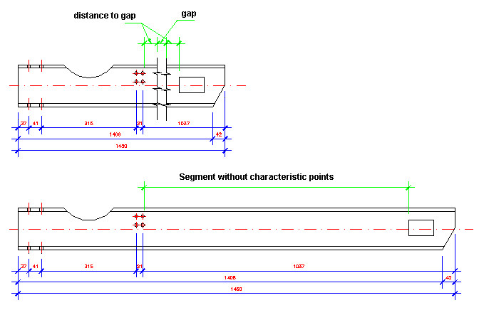
- Parts shortening - if this is selected, long elements (element segments that do not include any characteristic points) will be shortened in a final drawing. The element shortening is displayed as a gap in a shortened element.
Element shortening will be performed if the element segment (not including any characteristic points) is longer than a value of the user-defined minimal distance without details. The drawing below illustrates the same element, shortened (top part of the drawing) and not shortened (bottom part of the drawing).
You can define a type of break line to use during element shortening; the list contains all available line types in AutoCAD®, saved in a DWG format file. Thickness and color of the break line are identical to those of an element contour.
Additional parameters of shortening can be specified (see drawing below): gap value, and value of the distance to gap (distance between a characteristic point and a gap).
- Invisible edges - if this is not selected, invisible edges of an element are hidden in a final drawing. If this is selected, invisible edges are displayed in a drawing (specify their line color, line type, and line thickness parameters at the right of the option)
- Axes - if this is not selected, profile axes are hidden in a final drawing. If this is selected, profile axes are displayed in a drawing (specify their line color, line type, and line thickness parameters at the right of the option). Profile axes are displayed in all projections; in final drawings, axes are extended by 5 mm outside an edge of a dimensioned object
- User parts - if this is not selected, user parts are hidden in a final drawing. If this is selected, user parts are displayed in a drawing (specify their line color, line type, and line thickness parameters at the right of the option)
- Cut parameters - click this to open another dialog, in which you can specify parameters of section hatching and parameters of designation of a part section.
For styles of assemblies or groups, Distance to the first dimension line indicates the distance measured to the edge determined by a rectangle describing an assembly projection (rectangle sides are parallel to the axes of the element local coordinate system).
When defining a modification of an assembly style, the Draw parts in actual location option is available. If this is not selected, projections of an assembly are generated in the coordinate system determined by the main part of the assembly. If this is selected, projections of the assembly are generated in the WCS (the Global coordinate system).