Use this macro to define a castellated section beam.
To begin defining a castellated beam, open the Special profiles dialog from:
- Menu: Steel > Castellated beam
- Ribbon: ASD - Model > Elements > Castellated beam
- Toolbar: Plate girders > Castellated beam

- Command line: RBCT_MMACRO.
In the drawing area, click to specify the beginning and end points of a castellated beam.

A castellated beam is made by welding together longitudinally cut webs of rolled I-sections (types: 10-15, 20-25, 30).
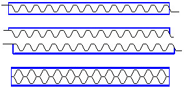
Types of castellated beam:
- Profile with hexagon-shaped openings
- Profile with hexagon-shaped openings (with a spacer plate)
- Profile with round openings
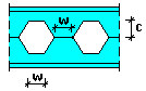 |
Hexagonal openings: c - cut depth w - distance between openings Chamfer angle: 60° |
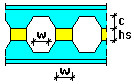 |
Hexagonal openings with a spacer plate: c - cut depth w - distance between openings hs - height of a spacer plate Chamfer angle: 60° |
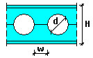 |
Round openings: d - opening diameter w - distance between openings H - section height. |
Define the following parameters of a castellated profile in the top part of the dialog:
- Profile type (I-section)
- Material
- Family
Profiles available on the selection list of profile types are those defined in the Profile List dialog. To add a profile to the list, click ![]() . The Profile list dialog displays, where you can select a profile.
. The Profile list dialog displays, where you can select a profile.
Use the options at the middle of the dialog:
- Insertion line – specify the location of the line of insertion of a castellated beam profile
- Middle - the insertion line coincides with the axis passing through the center of gravity
- Lower - the insertion line is situated in the middle of the outer surface of the lower flange
- Upper - the insertion line is situated in the middle of the outer surface of the upper flange
- Rotation – to define the angle of rotation of a profile with respect to the insertion line, select an available value (90, 180, or 270) or enter a different value.
- Weld type - select the type of welds that join parts of a castellated beam and that determine thickness of welds.
At the bottom of the dialog is the Use template selection field, which contains user-defined templates (schemes) of castellated beams. After you define castellated beam geometry, you can save the settings by typing a name in the Use template field and clicking Save as template. In the future, after you begin to define a castellated beam, you can select the name of a saved template so that all its parameters will be applied to the new castellated beam.
Use the buttons at the bottom of the dialog:
- Apply - after you click this, a castellated beam defined in the dialog is generated on the screen without closing the dialog. This lets you check whether the beam has been generated correctly.
- OK - click this to generate the defined castellated beam and close the dialog.
- Hide - after you click this, the dialog is no longer visible on the screen. To restore the dialog display on the screen, press Esc.
- Close - click this to close the dialog without generating a castellated beam.