You can define a girder plate (column).
To begin defining a girder plate, select the option from:
- Menu: Steel > Plate girders > Column
- Ribbon: ASD - Model > Elements > Column
- Toolbar: Plate girders > Column
 .
.
A column may consist of 5 to 10 plates connected by means of workshop welds. Column elements are displayed in the drawing below (the drawing was prepared with the Parallel flanges option switched off).
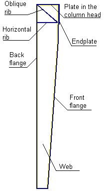
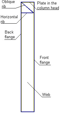
A web is made of 1 or 2 plates (depending on the Division of web option). Oblique and horizontal ribs are symmetrical with respect to the web (each of the ribs is composed of 2 plates set symmetrically with respect to the web). The front flange may consist of 1 part (1 plate along the entire length of a column - Continuous front flange selected) or 2 parts:
- a vertical flange in the upper part of the column and a flange inclined at a certain angle (the Parallel flanges option switched off).
- a vertical flange in the upper part of the column and a vertical flange in the lower part of the column (the Continuous front flange option switched off).
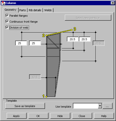
Point 1 is the beginning point of a plate girder (the first point defined in a drawing), positioned at the lower part of the column in the middle of the back flange. Point 2 is the end point of a plate girder (top point of the column), positioned in the upper part of the column in the middle of the back flange, and point 3 defines the incline of the upper part of the column (for example, it may be the point which determines the roof ridge in a frame).
Click Select new points in order to define a new position for a defined column (the column is moved from its current position to the new one).
Define column dimensions:
- Column width in the lower part
- Column width in the upper part
- Lengths of strengthening elements (endplate, plate in the column head, oblique and horizontal ribs)
- Length of the upper part of the web (if the Division of web option is switched on)
- Length of the column segment of constant cross-section
Define other parameters:
- Parallel flanges
- If this is not selected, the front flange is composed of plates, one of which may be inclined, and Continuous front flange is not available.
- If this is selected, the front flange is made of a plate parallel along the entire length to the back flange, and Continuous front flange is available.
- Continuous front flange (available only when Parallel flanges is selected)
- If this is selected, the front flange is made of 1 plate parallel along its entire length to the back flange (see the drawing below).
- If this is not selected, the front flange is made of 2 plates connected with each other by welds of user-defined lengths.
- Division of web
o If this is selected, a column is created with a web divided into an upper and a lower plate; the length of the upper part of the web should be defined.
o If this is not selected, the web is composed of 1 plate along the entire length of a column.
After you finish defining the plate girder dimensions, click the Parts tab to display the Column - Parts dialog.