The Bent parts dialog displays after you click Options in the Dimensioning style settings dialog (the option is available for curved parts presented in a developed form).
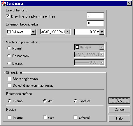
The dialog includes the following fields:
- Line of bending - use these options to define parameters of bending edges
- Machining presentation - use these options to determine how to display machining in a drawing; selection lists in the right part of the field are accessible only when Distinct is selected.
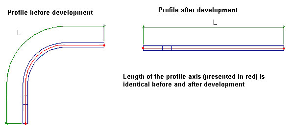
The idea of element development consists in transforming the curve representing the element axis into a straight line in such a way so that the axis length and distances between points on the axis remain the same (see the drawing below).
The line of bending is positioned in the middle of each arc-shaped segment. Color, type, and thickness of the line are defined in the bottom part of the Line of bending field.
The line of bending is displayed in a drawing if you select Draw line for radius smaller than. A radius value may also be specified (the line is usually drawn for small radiuses).
For Extension beyond edge, define a value of distance (extension of the line beyond the element edges on both sides of the element).
Under Machining presentation, select a presentation type (NOTE: the options below are not available in version 5.0):
- Normal - if this is selected, all openings, cuttings, and so on, will be displayed in a drawing consistently with the style adopted for standard parts
- Do not draw - if this is selected, only the profile shape will be displayed in a drawing (machinings will not be shown)
- Distinct - if this is selected, machinings will be displayed in a drawing; a shape of developed machinings will be defined identically as for normal presentation type. In addition, use the selection lists to specify thickness, color, and line type parameters.
Curved parts are dimensioned in the same manner as rectilinear parts. You can switch off dimensioning of machinings that may be shown in a drawing of a developed part. If you select Do not dimension machinings, all dimension points defining machinings are disregarded and only total dimensions and dimenions to the line of bending are displayed.
The options in the lower part of the dialog refer to drawings of developed bent plates. These drawings display the original shape and dimensions of plates (without plastic deformations).
Use these options to insert the following items in a drawing: bending lines, angle of bending, radius (external or to axis), dimensions, and machinings of a plate.
See also: Bending of plates